GE MEDICAL SYSTEMS PROPRIETARY TO GE
D
IRECTION 2294854-100, REVISION 3 LOGIQ™ 9 PROPRIETARY MANUAL
Chapter 5 Components and Functions (Theory) 5-47
5-10-2 Input Signals
5-10-3 Bi-directional Signals
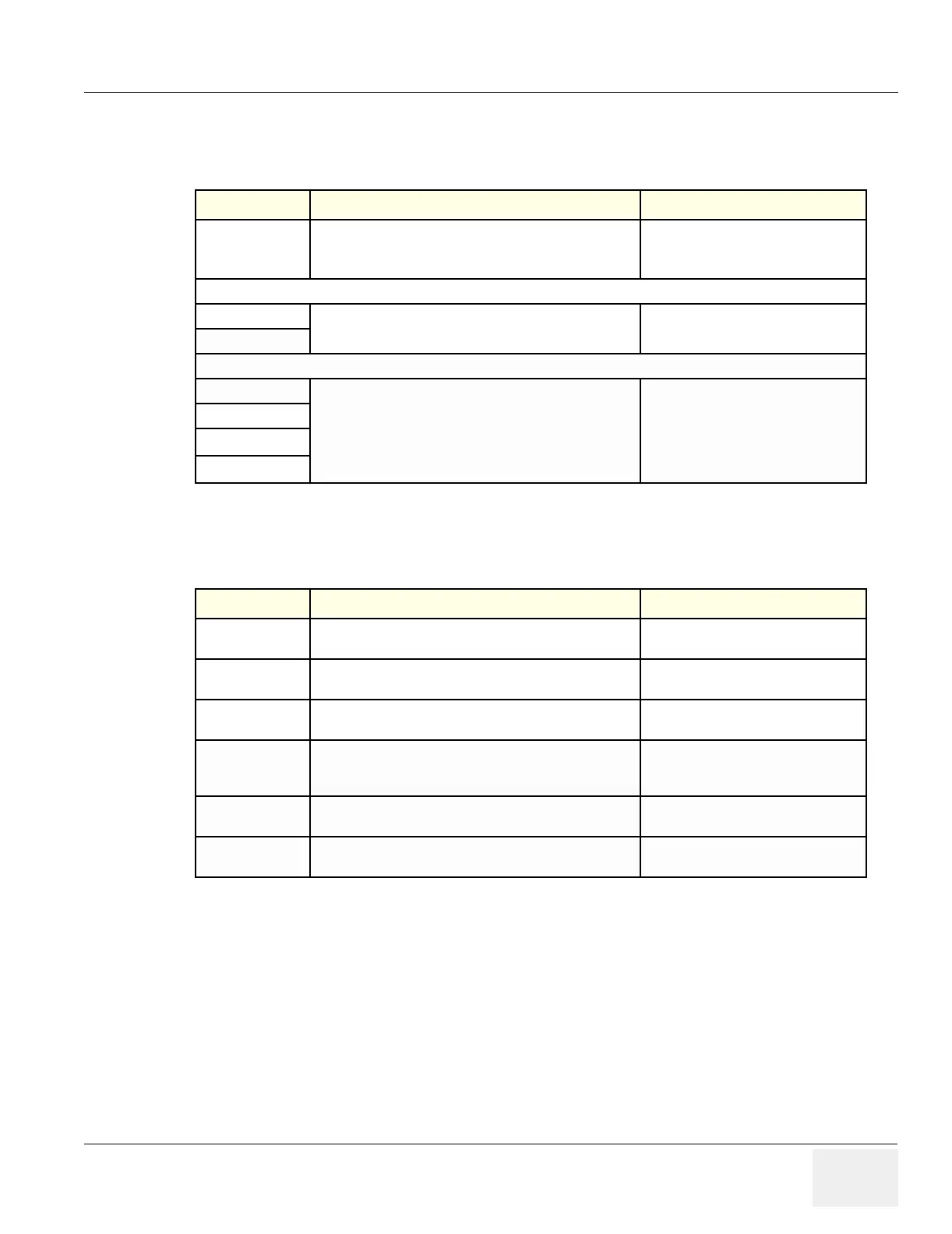
Table 5-29 Input Signals
Input Description Connection from/via/to
Footswitch
Connector
Footswitch is a mechanical switch that connect a signal to
ground.
Internal level is TTL (0-3.3V)
Footswitch > External I/O > Internal I/O
> PC2IO (BEP)
DC Voltages from BEP
+5 VDC
Used for Optical Couplers on RS232 signals
PC2IO (BEP) > Internal I/O > External I/
O
+12 VDC
DC Voltages from Card Rack
+5 VDC
Used for Optical Couplers on Footswitch
Card Rack > Internal I/O > External I/O
+15 VDC
-5 VDC
analog
+6 VDC
analog
Table 5-30 Bi-directional Signals
Signal Name Description Signal Path
Ethernet Standard 10/100 Base TX Ethernet
Ethernet - External I/O - Internal I/O -
BEP (Ethernet Connector)
COM1
Serial RS-232 port (Can be configured to transfer report
page data to an external processor)
External Device - External I/O - Internal
I/O - BEP (COM1)
USB Standard USB (Universal Serial Bus), (0-5V)
USB Device - External I/O - Internal I/O
- BEP (USB #2))
Modem Internal Modem Telephone Line Connection
Analog Phone Line - External I/O
(Connector Panel) - External I/O (Rear
Side)- Modem
COM2
Serial RS-232 port
(on rear side of External I/O)
Modem - External I/O
(Rear Side) - Internal I/O - BEP (COM1)
Burn-in Power On/
Off Control
Burn-in Power On/Off Control (on rear side of External I/O)
- Used for factory testing.
External I/O (Rear Side) - Internal I/O