GE MEDICAL SYSTEMS PROPRIETARY TO GE
D
IRECTION 2294854-100, REVISION 3 LOGIQ™ 9 PROPRIETARY MANUAL
5-44 Section 5-7 - Internal I/O
5-7-6Outputs (cont’d)
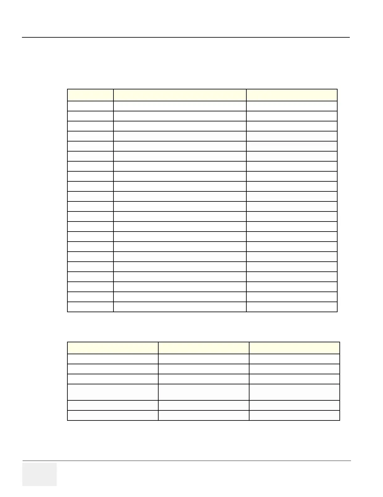
Interface Connectors – Component Side
Table 5-27 Connectors, Component Side
Input Description Connection from
A1/J1 B&W printer, 15pins HD-sub, female.
A2/P4 VCR remote ctrl – RS232: 9pins D-sub, male.
A3/P5 Color printer - RS232: 9pins D-sub, male.
A4/J2 Top Console - Power & signals: 15pins D-sub, female.
A5/P4 Top Console - Signals: 15pins D-sub, male.
A6/J6 Audio out to VCR, left: Phono jack.
A7/J7 Audio out to VCR, right: Phono jack.
A8/J8 Audio in from VCR, left: Phono jack.
A9/J9 Audio in from VCR, right
A10/J10 SVHS out to VCR
A11/J11 SVHS in from VCR
B1/J12 USB to Top console
B2/J13 USB to external I/O
B3/J14 Ethernet
B4/J15 Audio I/O
B5/J16 PC2IO signals
B6/J17 PC2IO power
B7/P18 COM1
B8/P19 COM2
B9/P25 UPS remote control
J32 MBD – signals and power
Table 5-28 Connectors, Solder side
Input Description Connection from
A12/J21 Spare power, 15pins D-sub, female
A13/J20 Spare – power, 15pins D-sub, female
A14/J24 AC power ctrl, 9pins D-sub, female
A15/P23
Rotation adapter – signals, 15pins D-
sub, male
A16/P22 Spare – signals, 25pins D-sub, female
P30 EIO – signals and power, 110pins male