GE MEDICAL SYSTEMS PROPRIETARY TO GE
D
IRECTION 2294854-100, REVISION 3 LOGIQ™ 9 PROPRIETARY MANUAL
8-18 Section 8-3 - Back End Processor Replacement Procedure
8-3-6 Back-End Processor Installation Procedure (cont’d)
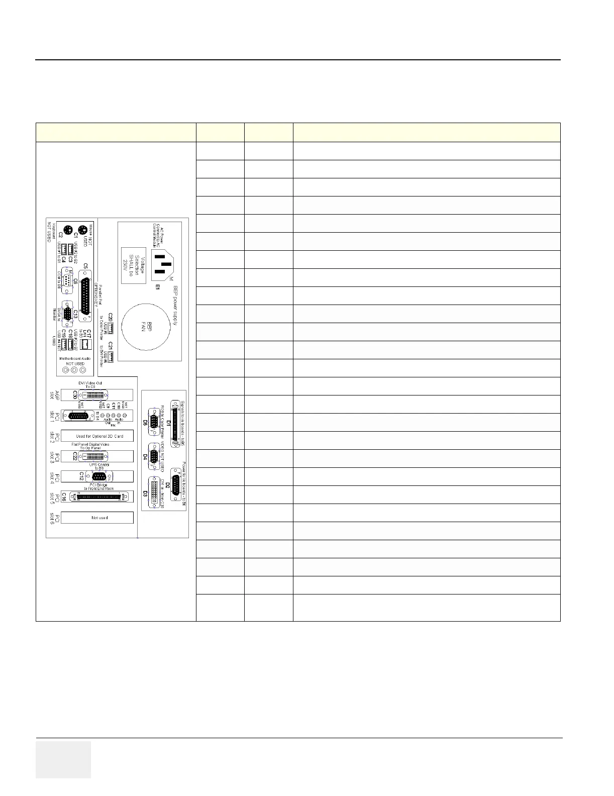
NOTE: A BEP 2.2 is the same as a BEP2.1 (DGVIC) with the extra 256MByte memory added. The
connector configuration is the same.
Table 8-6 BEP 2.1, BEP2.2 (P4) Back-End Processor Cable Identification
Number Slot Cable Function
C1
Mouse - Not used.
C2
Keyboard - Not used.
C3
USB #2 to Internal I/O B2
C4
USB #1 to Internal I/O B1
C5
Parallel Port - Options Dongle
C6
COM Port - Serial Port to Internal I/O B8
C13
Motherboard SVGA Video output to Monitot
C17
LAN to Internal I/O B3
C18
USB #3 to Internal I/O B7 (use USB to serial converter)
C19
USB #4 Not Used
C20
USB #5 to Digital Color Printer
C21
USB #6 to Digital B/W Printer
C30 AGP Slot
Digital Video to D3 DGVIC Input
C9 PCI Slot 1
Audio Out to Internal I/O B4 (Green)
C10 PCI Slot 1
Audio In to Internal I/O B4 (Blue)
C11 PCI Slot 1
Microphone to Internal I/O B4 (Pink)
PCI Slot 2
Optional 3D Card
C22 PCI Slot 3
Flat Panel; Digital Video To OP Panel
C12 PCI Slot 4
Power Supply UPS control - Connect to Internal I/O B9
C16 PCI Slot 5
PCI Bridge to the Front End Card Rack
PCI Slot 6
Not Used
D1 DGIO
Signals to I/O boards to Internal I/O B5
D2 DGIO
Power for I/O boards to Internal I/O B6
D3 DGVIC
Digital Video in from BEP ADD video board - C30
D4 DGVIC
SVGA Video output - Not Used
D5 DGVIC
RGB out to color printer (not used with Digital Color Printer)
 Loading...


