GE MEDICAL SYSTEMS PROPRIETARY TO GE
D
IRECTION 2294854-100, REVISION 3 LOGIQ™ 9 PROPRIETARY MANUAL
Chapter 8 Replacement Procedures 8-133
• FEPS2 Power Supply Differences
a.) There is more room to remove the PCI cable from the Scan Control Board and pull it through
the hole in the FEPS2.
b.) Two AC connections are still required but are mounted on front of the FEPS2 for easy access.
c.) The FEPS2 has two card ejectors so the screw in the bottom corner is not required to secure
the supply.
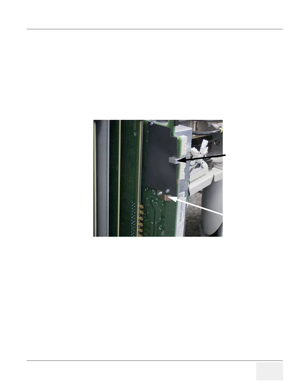
d.) A special copper ground tab and ground plane grabber are incorporated in the FEPS2 to
ensure good contact to the FEP card rack.
e.) A different FEP cover is needed, when an FEPS2 is installed, to add additional shielding
around the Top Plane Board connecting the XDIF to the RF Amp.
f.) It is important that ALL screws be used when replacing the Front End Processor Cover.
• FEPS3 Differences
a.) FEPS3 Power Supplies must be used with TD5 and RF AMP2 Front End card racks. The +/-
6V and 13V produced are required for these boards. Refer to Table 5-2 on page 5-6.
b.) Therefore, the FEPS3 can not be used with Front End card racks prior to R3.0.0 Software
(BT’03).
Figure 8-143 FEPS2 Grounding Points
Copper Grounding
Tab
Ground Plane
Grabber