CHAPTER 7
153
Gerber Solara ion Web Pages
4/29/10 Rev G
add the new value (-5) to it, and enter -7 in Cyan Left field. Continue to enter the new
alignment values for all the color print heads, Left and Right in the BI-DIR columns.
7 Click the Save Settings button to accept the values.
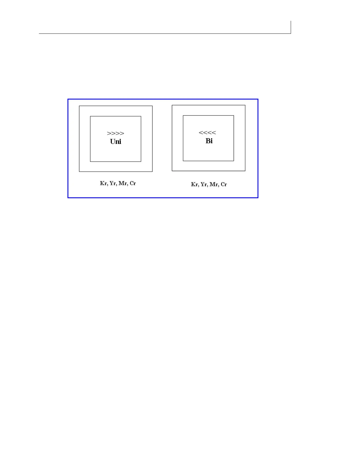
8 Reprint the job and make adjustments to values on Head Calibration page until all the
bidirectional box prints show best alignment position to be at zero position (center of
box), +/- 1.
9 By looking at the thickness in the vertical lines of these boxes, you can verify your
electrical alignments (360 Uni and 360 Bi) were done correctly.
10 The thickness of the line should be less than .020" (0.508mm).