13. Barometric pressure signal (Orange)
14. Air temperature sensor (White-Grey)
17. Idle adjustment motor (Sky Blue-Red)
18. Idle adjustment motor (Sky Blue-Black)
19. Idle adjustment motor (Orange-Red)
20. Sensor negative (Sky Blue-Green)
22. Sensor positive (Red-Blue)
25. Engine rpm sensor (White)
28. Cylinder 1 injector (Red-Yellow)
29.Throttle valve potentiometer (Grey-Black)
32.Throttle valve potentiometer (Brown-Yellow)
34. Engine rpm sensor shield (Black)
35. Engine rpm sensor (Red)
37. Cylinder 2 injector (Blue)
38. Cylinder 1 HV coil (Pink-Black)
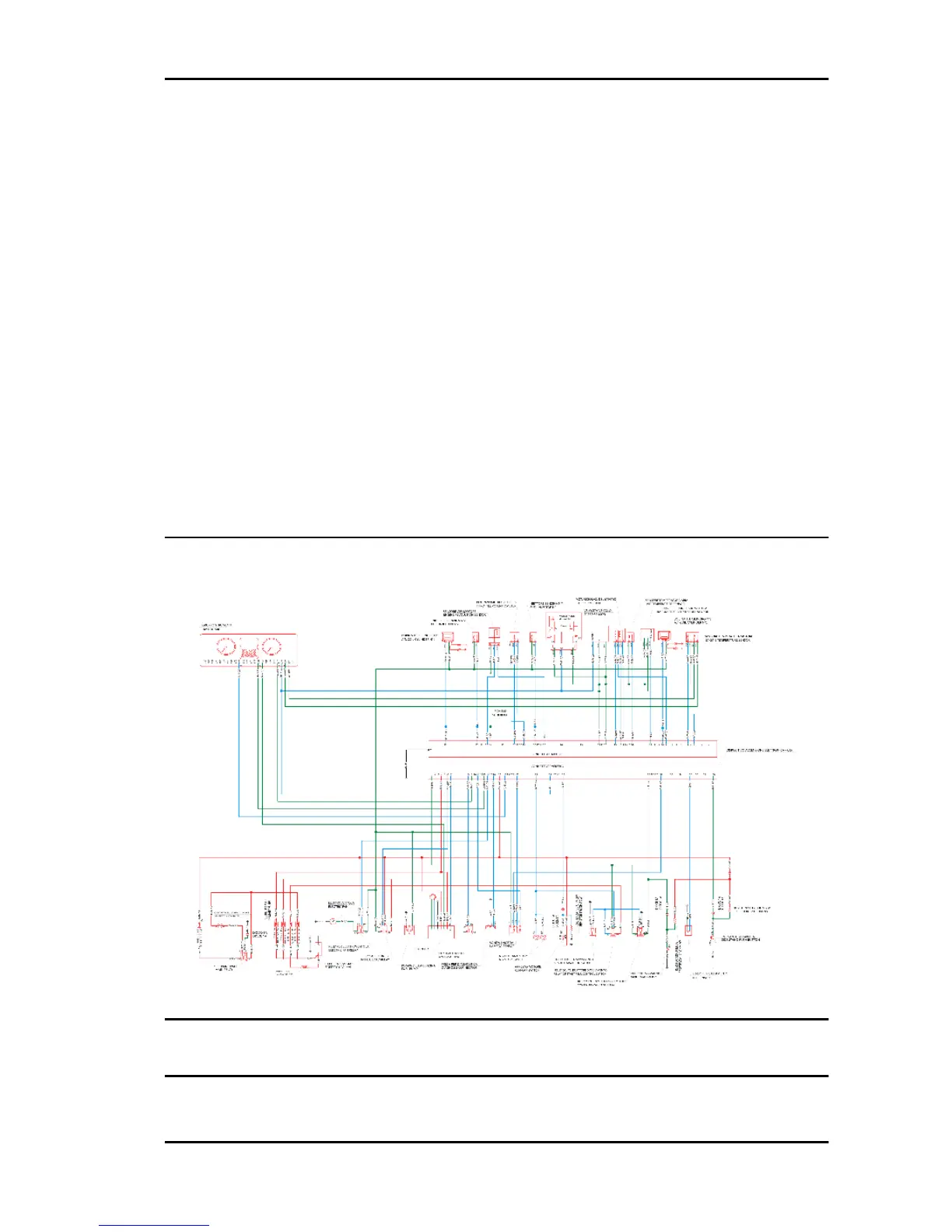
EMS circuit diagram
Troubleshooting procedure
GP 800 i.e. Injection
INJEC - 7