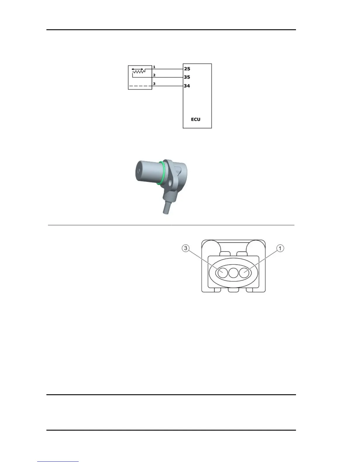
ENGINE RPM SENSOR CONNECTOR
1. Control unit (White)
2. Control unit (Red)
3. Sensor shield (Black)
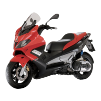
REVOLUTION TIMING SENSOR
Resistance between "+ and -" = 890 ± Ohm (pins 35 - 25 , engine-side wiring)
Insulation between "+ and S" and between "- and S" (pins 35 - 34 and 25 - 34, engine-side wiring)
Check the continuity between pin 1 of the revolution timing sensor connector and pin 25 of the engine
connector control unit. Check the continuity between pin 2 of the revolution timing sensor connector
and pin 35 of the engine connector control unit. Check insulation between them and the ground lead of
pin 1 and 2 of the connector and shielding. Check the continuity between pin 3 of the connector and
pin 34 of the engine connector control unit.
Injection GP 800 i.e.
INJEC - 22