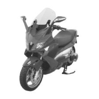
0.1 ÷ 0.45 mm (when cold)
- Using a bore gauge, measure the connecting rod
small end diameter.
N.B.
IF THE CONNECTING ROD SMALL END DIAM-
ETER EXCEEDS THE STANDARD DIAMETER,
EXHIBITS WEAR OR OVERHEATING, PRO-
CEED TO REPLACE THE CRANKSHAFT AS
DESCRIBED IN CHAPTER CRANKCASE AND
CRANKSHAFT.
Characteristic
Standard diameter:
22 + 0.025 +0.015 mm
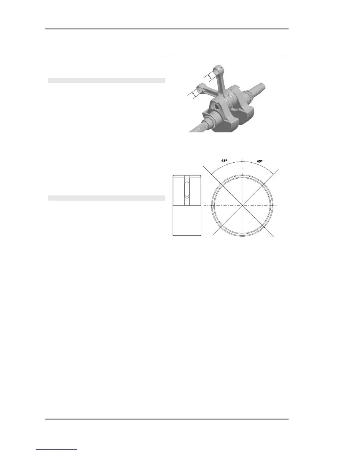
- Check the inside diameter of the main bushings
in the three directions indicated in the diagram.
- Repeat the measurements for the other bushing
half. see diagram.
N.B.
DO NOT TAKE THE MEASUREMENT ON THE
TWO HALF-SHELL COUPLING SURFACE
SINCE THE ENDS ARE RELIEVED TO ALLOW
BENDING DURING THE DRIVING OPERATION.
Before assembling, check that the clearance between the engine crankcase bushing and the crankshaft
is within the predetermined limits.
Characteristic
Crankshaft-bushing maximum clearance admitted:
0.08 mm
- The standard bushing diameter after driving is variable on the basis of a coupling selection.
- The bushing seats in the crankcase and the crankshaft are classified into 2 categories.
- Bushings are subdivided into 3 categories according to their thickness (see the table).
The following kinds of bushings indicated in the table must be used according to the kind of coupling
between the crankshaft and the crankcase.
Characteristics GP 800 i.e.
CHAR - 22