EasyManuals Logo

GW Instek GDM-906 Series User Manual

GW Instek GDM-906 Series
368 pages
To Next Page IconTo Next Page
To Previous Page IconTo Previous Page
Page #112 background imageLoading...
Page #112 background image
GDM-906X Series User Manual
112
5
Pass Out
Clock
OUT1
6
Fail Out
Output Enable
OUT2
7
High Limit Fail
Out
Strobe
OUT3
8
Low Limit Fail
Out
Serial Input
OUT4
9
EOM Out
EOM Out
EOM Out
Pin1
VCC output, 5V. Serves as the unregulated max power
source for the external device/logic.
The maximum current is 100mA.
Pin2
Flyback Diode. Connect to VCC or External power
source.
Pin3
Digital (chassis) Ground.
Pin4
External Trigger Input. Accepts external trigger
signals. For using external signals.
Pins 3-4 output
wiring diagram
Pin5-8
Pin 5-8 are designed as composite pins, which can be
specified by user for diversified functions as follows:
Compare/4094/User Mdoe
Refer to the page 113 for details of Compare Mode,
and the page 120 for details of 4094/User Mode.
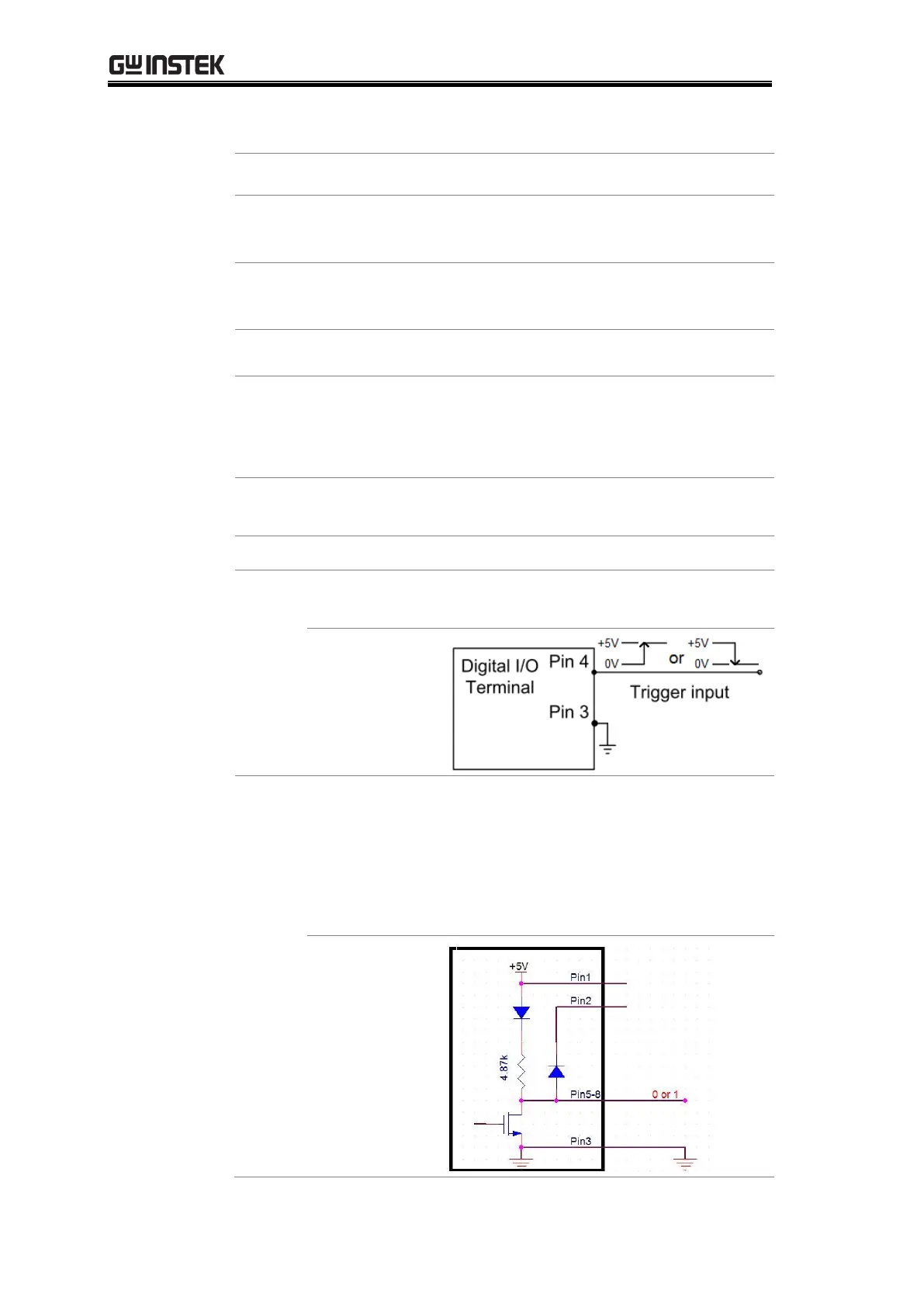
Pins 5-8 output
wiring diagram

Table of Contents

Questions and Answers:

Question and Answer IconNeed help?

Do you have a question about the GW Instek GDM-906 Series and is the answer not in the manual?

GW Instek GDM-906 Series Specifications

General IconGeneral
BrandGW Instek
ModelGDM-906 Series
CategoryMeasuring Instruments
LanguageEnglish

Related product manuals