EasyManuals Logo

GW Instek GDM-906 Series User Manual

GW Instek GDM-906 Series
368 pages
To Next Page IconTo Next Page
To Previous Page IconTo Previous Page
Page #111 background imageLoading...
Page #111 background image
DIGITAL I/O
111
Digital I/O Overview
Background
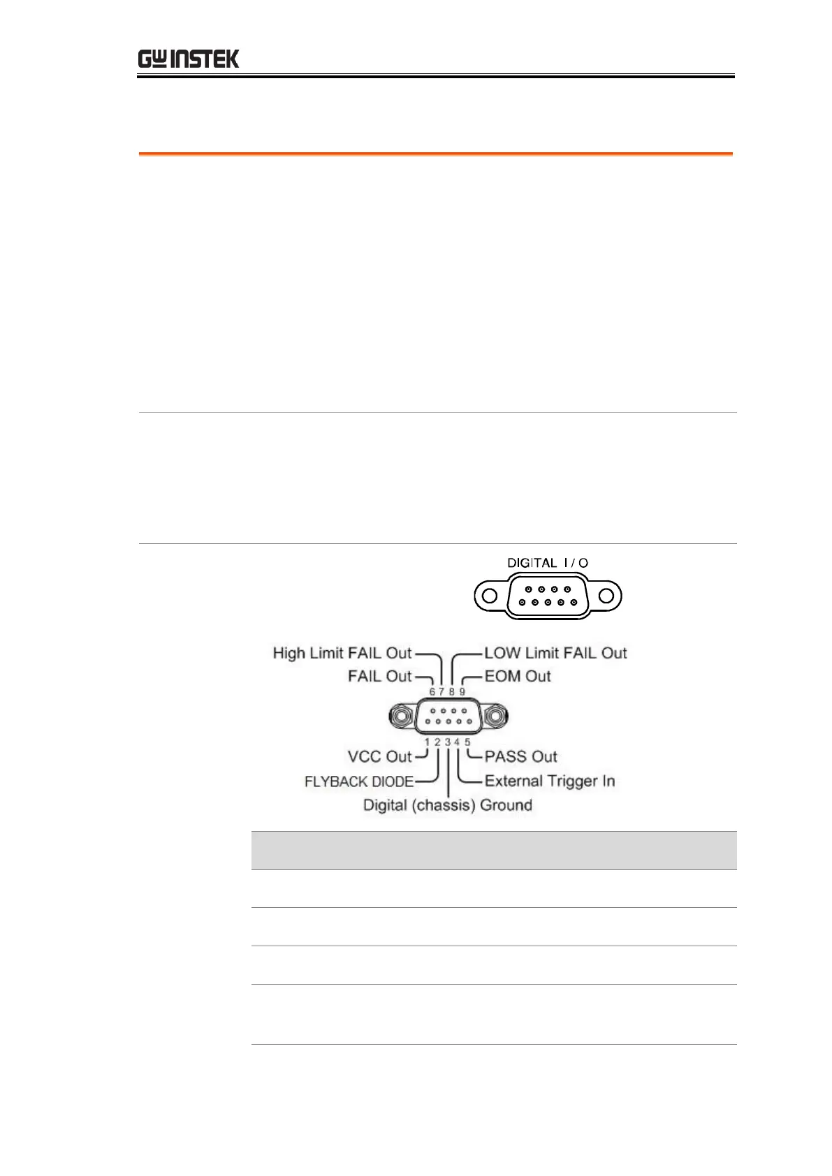
The Digital I/O port is a triple function port. By default
(Compare Mode) the port is used with the compare function to
output Hi Fail, Lo Fail, Pass, and EOM (end of measurement)
signals. In addition, there is also a TRIG IN input pin.
As a secondary function (4094 Mode) and third function (User
Mode), the Digital I/O port can have the output state of pins
5 ~ 8 controlled via remote control.
By providing separate VCC power for the terminal, the outputs
can also be used as a power source for TTL and CMOS
circuits.
Related
Commands
DIGital:INTerface:MODE ?
DIGital:INTerface:MODE {COMP|4094|IO}
DIGital:INTerface:DATA:OUTPut (For 4094 Mode)
DIGital:INTerface:DATA:SETup (For User Mode)
Pin
Assignment
Connector type: DB-9
female
Pin No
Compare Mode
4094 Mode
User Mode
1
VCC Out
VCC Out
VCC Out
2
Flyback Diode
Flyback Diode
Flyback Diode
3
Digital Ground
Digital Ground
Digital Ground
4
External Trigger
In
External Trigger
In
External Trigger In

Table of Contents

Questions and Answers:

Question and Answer IconNeed help?

Do you have a question about the GW Instek GDM-906 Series and is the answer not in the manual?

GW Instek GDM-906 Series Specifications

General IconGeneral
BrandGW Instek
ModelGDM-906 Series
CategoryMeasuring Instruments
LanguageEnglish

Related product manuals