EasyManuals Logo

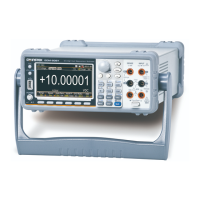
GW Instek GDM-906 Series User Manual

GW Instek GDM-906 Series
368 pages
To Next Page IconTo Next Page
To Previous Page IconTo Previous Page
Page #122 background imageLoading...
Page #122 background image
GDM-906X Series User Manual
122
User Mode – Switch Mode (LED)
Overview
It is the mode driving LED as status display for user with up
to 4 pins available for use simultaneously. Refer to the
following introductions along with diagrams for more details.
Please see the digital I/O commands on page 272 for full
usage details.
Related
Commands
DIG:INT:MODE IO (switch to IO mode)
DIG:INT:DATA:SET 1,0,0,1
=> OUT1(Pin5) : LED OFF
OUT2(Pin6) : LED ON
OUT3(Pin7) : LED ON
OUT4(Pin8) : LED OFF
Pin
Assignment
Pin No
User Mode
Description
1
VCC Out
Option(Vcc:+5V)
2
Flyback Diode
No Use
3
Digital Ground
Option(GND)
5
OUT1
Use
6
OUT2
Use
7
OUT3
Use
8
OUT4
Use

Table of Contents

Questions and Answers:

Question and Answer IconNeed help?

Do you have a question about the GW Instek GDM-906 Series and is the answer not in the manual?

GW Instek GDM-906 Series Specifications

General IconGeneral
BrandGW Instek
ModelGDM-906 Series
CategoryMeasuring Instruments
LanguageEnglish

Related product manuals