MAN0923_Issue 3_04/15 Touchpoint Pro
Operating Instructions
104
7. Normal Operation
Note: When you manually place an Output Relay into ‘Inhibit’, it holds the Relay in the current state. I.e. if
the Relay is in a Normal (Healthy) state at the time of ‘inhibit’ it stays in that state and, if the Relay is in an
Alarm (Non- Healthy) state at the time of ‘inhibit’ it stays in that state. An Alarm state cannot be ‘over-ridden’
by an ‘inhibit’ of the output Relay.
It is possible to have more than one inhibit condition active on a channel, and you have to resolve all inhibit
conditions before the inhibit can be cleared.
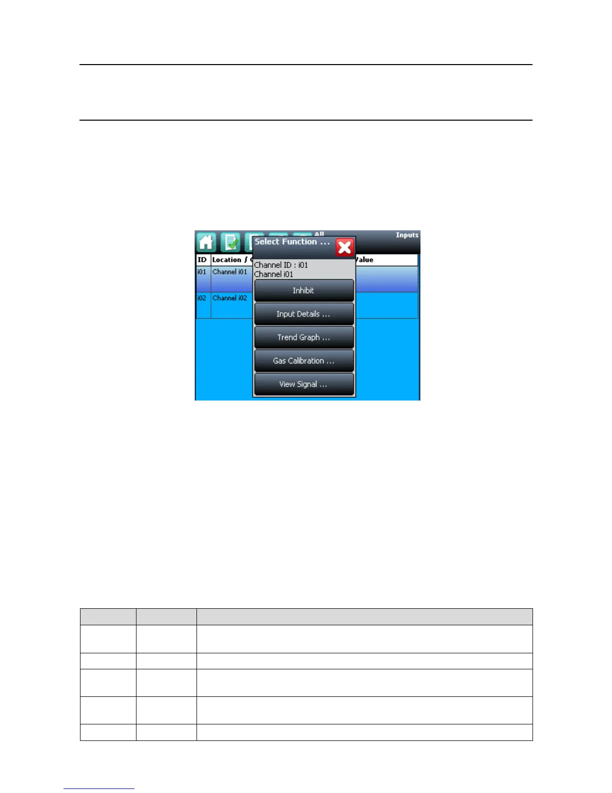
Figure 7.12 Inputs Screen with menu options
7.7 View Input Channels and Input Details
Note: In the Touchscreen view, the Inputs and Outputs icons toggle – from the System Status screen
navigation bar only the Inputs icon is visible, the Outputs icon is visible from the Inputs screen and vice
versa.
1. From the System Status screen navigation bar, select the Inputs icon
2. A list of all input channels is shown in order of channel ID. The channel ID, location tag, gas name,
status and current reading are shown
3. Thelistcanbelteredbystatus–Alarm,Fault,Inhibit,WarningorAll
4. Select a channel. Depending on access level, a number of options are shown
Function Access Level Comment
Inhibit Engineer
Inhibits the channel. On an inhibited channel, this option is Clear Inhibit. See Normal Operation,
Inhibit for more information.
Calibration Engineer Option to calibrate the channel. See Commissioning, Calibration for more information.
Trend Graph View Shows the trend graph for the channel. See Normal Operation, View Trend Graph for more
information
Input Details View Shows detailed information about the channel including Custom ID, sensor and gas name, gas
reading, configured alarms and alarm levels
View Signal Administrator Shows the raw signal being received on the channel