MAN0923_Issue 3_04/15 Touchpoint Pro
Operating Instructions
62
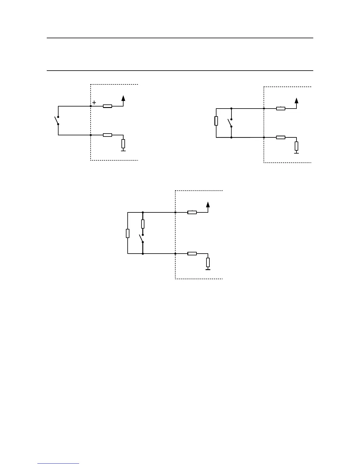
4. Electrical Installation
TPPR
SWITCH
+24 Vdc
1KΩ
75 Ω
0 Vdc
-
Figure 4.16 Unsupervised conguration
TPPR
SWITCH
+24 Vdc
10KΩ
R
EOL
1KΩ
75 Ω
0 Vdc
+
-
Figure 4.17 Supervised for open
circuit conguration
TPPR
SWITCH
+24 Vdc
10KΩ
2.7KΩ
R
EOL
R
INL
1KΩ
75 Ω
0 Vdc
+
-
Figure 4.18 Supervised for open and
short circuit conguration
4.8.7 Relay Output Module
Note: Channel wiring is from left to right for terminals on the top and bottom of the module. It is not
possible to move a plug from top to bottom of a module after wiring.
Please ensure correct wiring by system verication tests. See Commissioning, First Time Switch On, and
Maintenance, Testing the Touchpoint Pro System
TheRelayOutputModule(ROM)providesrelayoutputstoswitchelddevicessuchassounders,beacons
and actuators. In addition, an auxiliary voltage supply is available to provide power to such devices.
The relay contacts have a recommended range of application ≥ 12 Vdc, 10 mA. The maximum contact
current rating is 5 A per channel, with the additional limitation that the maximum contact current rating
forthemoduleis8A.Anovercurrentprotectiondeviceshouldbettedtopreventhighercurrentowing
through the relay contacts.

 Loading...


