MAN0923_Issue 3_04/15 Touchpoint Pro
Operating Instructions
61
4. Electrical Installation
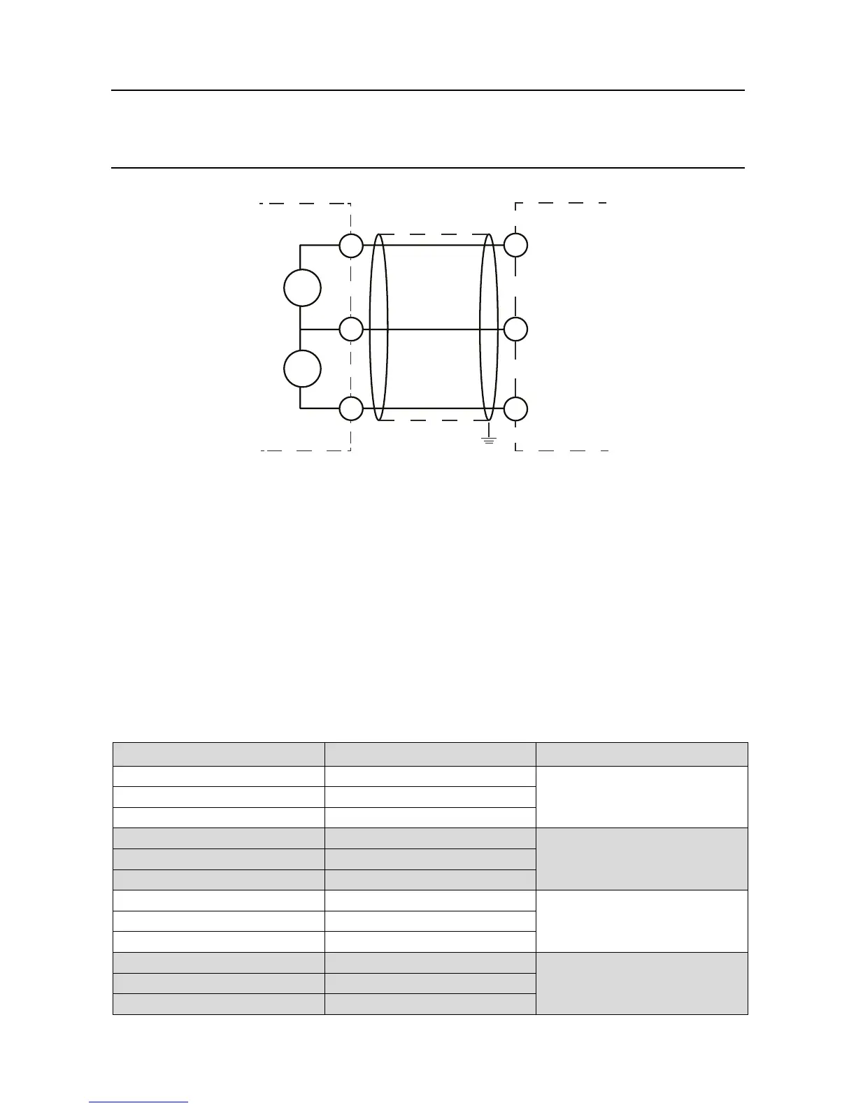
S
S
01
S
+
_
NS
NS
Catalytic Detector Touchpoint Pro
Figure 4.15 Catalytic detector
4.8.6 Digital Input Module
Note: Channel wiring is from left to right for terminals on the top and bottom of the module. It is not
possible to move a plug from top to bottom of a module after wiring.
Please ensure correct wiring by system verication tests. See Commissioning, First Time Switch On, and
Maintenance, Testing the Touchpoint Pro System.
DIMshavetwomodesofoperation.ADIMchannelmaybeconguredtogenerateanalarm,faultor
warning signal when activated.
Alternatively,aDIMchannelmaybeconguredtoprovideremotecontrolofaselectedgroupofoneor
more input / output channels. The DIM may be used to remotely reset, inhibit, or acknowledge the selected
channels. When used for inhibit, repeated activation toggles the inhibit state of the selected channels.
Terminal Identication Label Channel
1 +
Input 1
2
3 -
4 +
Input 2
5
6 -
7 +
Input 3
8
9 -
10 +
Input 4
11
12 -