MAN0923_Issue 3_04/15 Touchpoint Pro
Operating Instructions
43
3. Mechanical Installation
10. Drill out the hole required for the cable entry.
Caution: Support the cable gland plate to avoid distortion.
11. Fit and lock cable glands to the cable entries. The cable glands should be appropriate to the application
and capable of maintaining the IP20 rating. The cable glands must provide anchorage and stress relief
for the incoming cables .
12.Re-tthecableglandplate.
13. Feed the cable through the glands.
14. Terminate the cable in accordance with Chapter 4 Electrical Installation.
15. On completion of installation, close and lock the enclosure door.
WARNING
Unauthorised modication of the Touchpoint Pro system or components is not allowed, as this
will invalidate the legal certications and may render the system dangerous or inoperable.
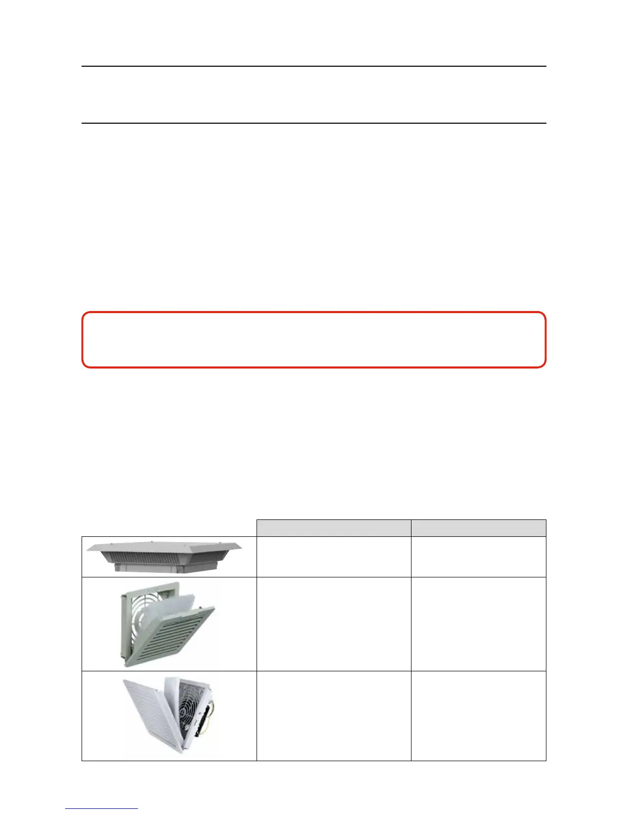
3.8 Cooling and Ventilation
The following items may be supplied with your purchase. They are an integral part of the cooling and
ventilation system, and they contribute to the IP rating, and should therefore not be removed. Attempting to
remove them may cause irreparable damage to the housings or components.
These items should be checked for cleanliness, dust and function as part of your normal maintenance
cycle. Faulty items must be replaced with an exact match item to maintain system integrity.
Description Part Number
Roof Exhaust Unit TPPR-V-1996
Door Inlet Vent and Replaceable Filter TPPR-V-1997
Door Inlet Fan and Replaceable Filter 24V
DC Filter Fan
TPPR-V-1999