MAN0923_Issue 3_04/15 Touchpoint Pro
Operating Instructions
184
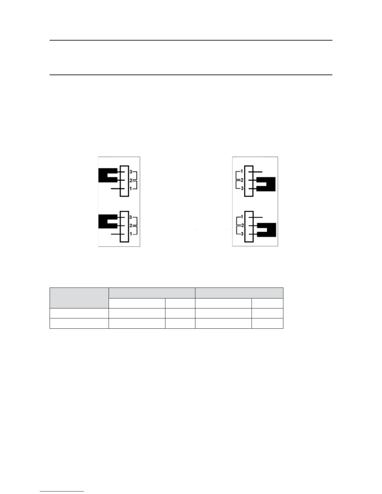
7. Set the jumpers for the appropriate channel to the “Termination On” position according to the diagram
and table below
8. CarefullyreplacethecoverontheControlModule,retandre-tightenthethreelocknutscrews
9. Retthecables
Note: The termination resistor should only be switched across a channel that forms the nal node of an
RS485 highway. It is necessary to set both jumpers for the channel.
PL3
PL4
Channel 1 (TB5) Channel 2 (TB6)
PL6
PL5
Termination Off
Termination Off
Termination Off
Termination Off
Termination On
Termination On
Termination On
Termination On
14.7 Jumpers for the Termination Resistance - default conguration
Setting Channel 1 Channel 2
PL3 PL4 PL5 PL6
Termination ON 1-2 1-2 1-2 1-2
Termination OFF 2-3 2-3 2-3 2-3
14.2.6 Multi-drop mode
For a multi-drop installation, a maximum of 32 nodes (31 slave nodes plus one master node) can be
supported.
14. Appendix 1 - Modbus Option

 Loading...


