TB5
5
Drain_TB6
A2_IN
B2_IN
A2_OUT
B2_OUT
5
Drain_TB7
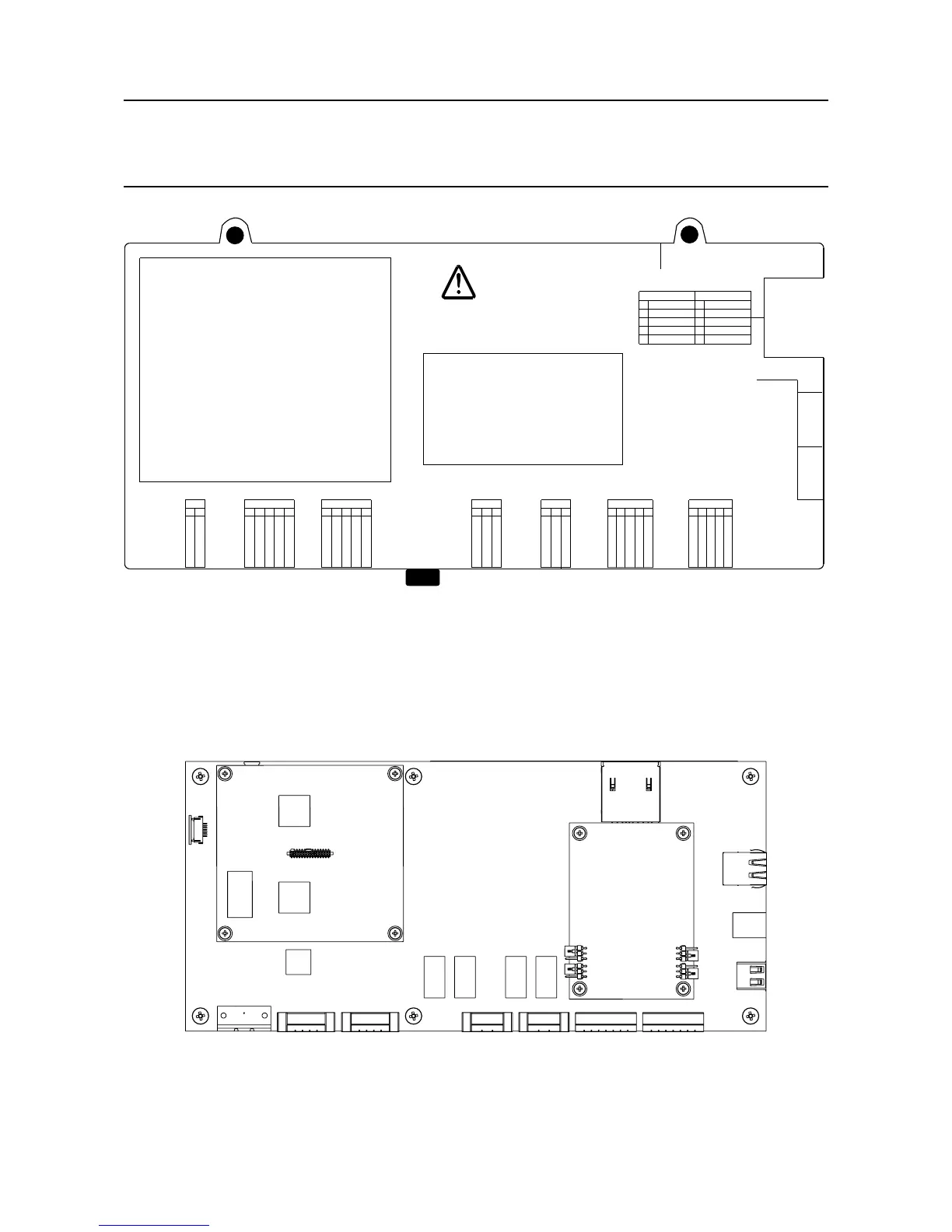
WARNING!
Remove top and bottom Plugs
of TB9, TB8, before opening the cover.
RS-485 Interface 2
Made in
XX
Product Label
2400D1370
5
4
3
2
1
TOP TB9
BOTTOM TB8
PSU4_Stat 1
Screen_TB9
PSU3_Stat 2
PSU4_Stat 2
PSU3_Stat 1
PSU2_Stat 1
Screen_TB8
PSU1_Stat 2
PSU2_Stat 2
PSU1_Stat 1
5
4
3
2
1
14.5 Removing the Control Module Cover
3. Remove the two M4 locknut screws at the top of the cover
4. Loosen the M4 locknut screw on the underside of the cover
5. Carefully slide the cover off
Bus Interface Board
14.6 Location of Bus Interface Board
6. Locate the Bus Interface Board (BIB) which is mounted on the right side of the Control Module
motherboard
14. Appendix 1 - Modbus Option
 Loading...


