MAN0923_Issue 3_04/15 Touchpoint Pro
Operating Instructions
182
R
T
R
T
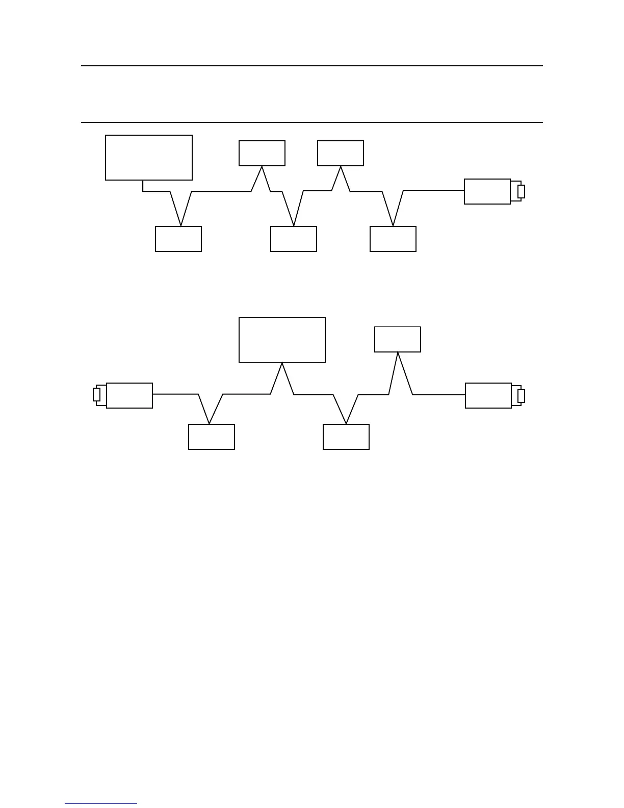
Modbus Master
(normally 120 ohm
termination resistance
Modbus Master
Disconnect 120 ohm
termination resistance
Slave
Node
Slave
Node
Slave
Node
Slave
Node
Slave
Node
Slave
Node
Slave
Node
Slave
Node
Slave
Node
Slave
Node
Slave
Node
R
T
14.4 Example Systems - Touchpoint Pro can be any one of the slave nodes
Alternatively,ifadifferentresistanceisrequiredforaspecicinstallation,donotchangethejumpersettings
but connect a resistor directly between terminals 3 and 4 (A OUT and B OUT) of TB6 and / or TB7 without
using the internal termination resistor.
To connect the termination resistor using the Touchpoint Pro jumpers located on the Bus Interface Board:
Caution: The SD Card, any USB device and all cables must be removed before attempting to remove
the Control Module cover panel.
1. Locate the cover panel of the Control Module
2. Remove all cables
14. Appendix 1 - Modbus Option
 Loading...


