MAN0923_Issue 3_04/15 Touchpoint Pro
Operating Instructions
219
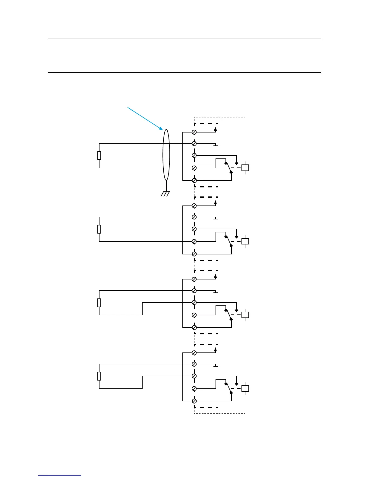
16. Appendix 3 - Wiring Diagrams
16.9 ROM With Internal Auxiliary Supply in NC and NO Conguration
0VDC
Channel 1
(NC Configuration)
+24VDC
C
3
NC
2
NO
1
+V
14
-V
15
ROM Module
0VDC
Channel 2
(NC Configuration)
+24VDC
C
6
NC
5
NO
4
+V
17
-V
18
0VDC
Channel 3
(NO Configuration)
+24VDC
C
9
NC
8
NO
7
+V
20
-V
21
0VDC
Channel 4
(NO Configuration)
+24VDC
C
12
NC
11
NO
10
+V
23
-V
24
R
LOAD
R
LOAD
R
LOAD
R
LOAD
E
Recommended Cable:
2 Core, Twisted, Mesh Type
Shielded, 1.5mm
2
or 2.5mm
2
Notes:
1. For all shielded cables, shield (screen) should be connected to Earth tag bar/bus bar provided in Touchpoint Pro enclosure.
2. Maximum +24Vdc Output Load, 1.5A per channel, and 1.5A total per module. With Overload protection.
3. Maximum Relay contact rating, 5A@ 24Vdc and 5A@230Vac (resistive loads only)