MAN0923_Issue 3_04/15 Touchpoint Pro
Operating Instructions
60
4. Electrical Installation
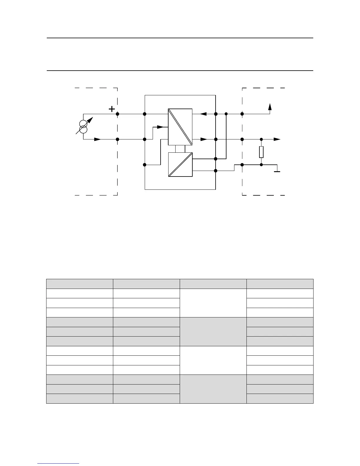
2 Wire Detector
4-20 mA
Touchpoint Pro
+24 Vdc
SIG
-V
101 Ω
0 Vdc
+V
Isolated Barrier
+vs
-vs
+ve
-ve
Figure 4.14 Two wire device with a isolated barrier
4.8.5 Analogue Input Module mV Bridge
Note: Channel wiring is from left to right for terminals on the top and bottom of the module. It is not
possible to move a plug from top to bottom of a module after wiring.
Please ensure correct wiring by system verication tests. See Commissioning, First Time Switch On, and
Maintenance, Testing the Touchpoint Pro System
Terminal Identication Label Channel Field device
1 S Input 1 Sensitive (+)
2 01 Signal
3 NS Non-sensitive (-)
4 S Input 2 Sensitive (+)
5 01 Signal
6 NS Non-sensitive (-)
7 S Input 3 Sensitive (+)
8 01 Signal
9 NS Non-sensitive (-)
10 S Input 4 Sensitive (+)
11 01 Signal
12 NS Non-sensitive (-)