MAN0923_Issue 3_04/15 Touchpoint Pro
Operating Instructions
211
16. Appendix 3 - Wiring Diagrams
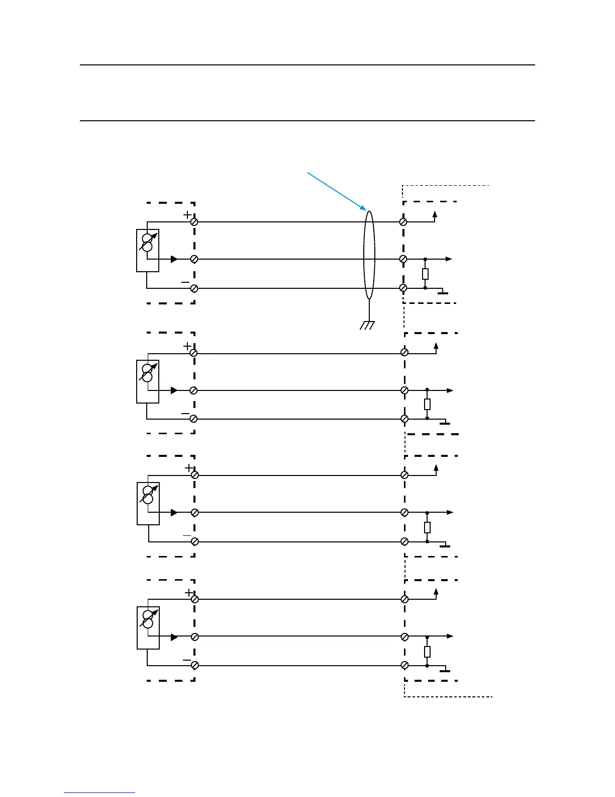
16.1 AIM 4-20 mA with 3 Wire Device Powered by AIM mA
3 Wire Detector
3 Wire Detector
3 Wire Detector
3 Wire Detector
4-20mA
4-20mA
4-20mA
4-20mA
Recommended Cable:
3 Core, Twisted, Mesh Type
Shielded, 1.5mm
2
or 2.5mm
2
AIM mA Module
Channel 1
Channel 2
Channel 3
Channel 4
Note:
1. For all shielded cables, shield (screen) should be connected to Earth tag bar/bus bar provided in Touchpoint Pro enclosure.
Input 1
Input 2
Input 3
Input 4
+24VDC
+24VDC
+24VDC
+24VDC
0VDC
0VDC
0VDC
0VDC
101 Ω
101 Ω
101 Ω
101 Ω
SIG
SIG
SIG
SIG
+V
+V
+V
+V
-V
-V
-V
-V
1
2
3
4
5
6
7
8
9
10
11
12
E