MAN0923_Issue 3_04/15 Touchpoint Pro
Operating Instructions
215
16. Appendix 3 - Wiring Diagrams
Recommended Cable:
2 Core, Twisted, Mesh Type
Shielded, 1.5mm
2
or 2.5mm
2
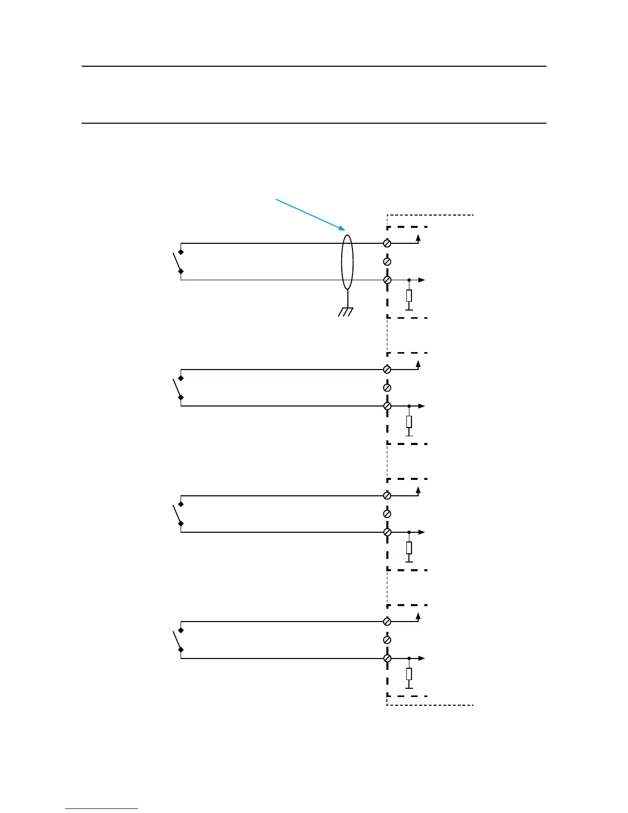
DIM Module
Notes:
1. For all shielded cables, shield (screen) should be connected to Earth tag bar/bus bar provided in Touchpoint Pro enclosure.
2. Switch can be manually operated push button or potential free contact.
3. Maximum current through closed contact limited to 15mA.
E
16.5 DIM in Unsupervised Conguration
Channel 1
+24VDC
0VDC
1.075 KΩ
+
-
1
2
3
Switch
Channel 2
+24VDC
0VDC
1.075 KΩ
+
-
4
5
6
Switch
Channel 3
+24VDC
0VDC
1.075 KΩ
+
-
7
8
9
Switch
Channel 4
+24VDC
0VDC
1.075 KΩ
+
-
10
11
12
Switch