MAN0923_Issue 3_04/15 Touchpoint Pro
Operating Instructions
178
14.2 Installation
14.2.1 Installing the Bus Interface Board (Upgrade or Assembly by system integrators)
Caution: All electronic hardware and PCB assemblies contain static sensitive components. Take
appropriate precautions to minimise the risk of electrostatic discharge.
Caution: The SD Card, any USB device and all cables must be removed before attempting to remove
the Control Module cover panel.
Ifnotalreadytted,theBusInterfaceBoardisinstalledasfollows:
1. Power off the supply to the system
2. Locate the cover panel of the Control Module
3. Remove all cables
System Label
Power Supply
TB1
1
2
24V DC
0V
Ring Network
1 2
3
4
Ring BO+
Ring BO-
Ring AI+
Ring AI-
TB3
1
2
3
4
Ring AO+
Ring AO-
Ring BI+
Ring BI-
TB2
1
2 3
SIS_Fail_COM
SIS_Fail_NO
TB5
5
Drain_TB6
A2_IN
B2_IN
A2_OUT
B2_OUT
5
Drain_TB7
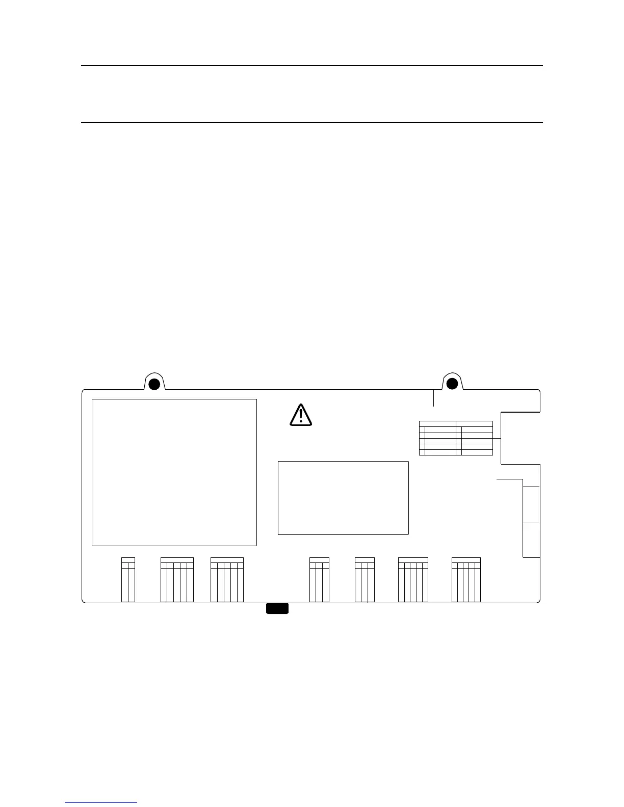
WARNING!
Remove top and bottom Plugs
of TB9, TB8, before opening the cover.
RS-485 Interface 2
Made in
XX
Product Label
2400D1370
5
4
3
2
1
TOP TB9
BOTTOM TB8
PSU4_Stat 1
Screen_TB9
PSU3_Stat 2
PSU4_Stat 2
PSU3_Stat 1
PSU2_Stat 1
Screen_TB8
PSU1_Stat 2
PSU2_Stat 2
PSU1_Stat 1
5
4
3
2
1
Figure 14.1 Removing the Control Module cover
4. Remove the two M4 locknut screws at the top of the cover
5. Loosen the M4 locknut screw on the underside of the cover
6. Carefully slide the cover off
7. Locate the position for the Bus Interface Board (four stand-offs (pillars) to the right side of the
Control Module motherboard)
8. Align the connectors and gently push into place
14. Appendix 1 - Modbus Option