MAN0923_Issue 3_04/15 Touchpoint Pro
Operating Instructions
21
2. Overview / Introduction
2.4 System Topology
Touchpoint Pro can be implemented using a centralised or distributed cabling architecture. With a centralised
architecture,allelddevicesarecabledbacktoacentralpoint(so-called“homerun”).Inadistributed
architecture,elddevicesareclusteredwithshortcablerunstoacontrolunit(inthiscasetheTouchpoin t Pro
Remote unit) and a minimal amount of cabling is required back to the central point (in this case only the Ring
Network cable). The only restrictions on a distributed architecture are the maximum round trip distance of 3
km and the maximum distance between two Touchpoint Pro units (Controller or Remote) of 1 km.
2.5 Communication / Power Rail and Ring Network
The Touchpoint Pro Communication / Power Rail directly provides power and network connection to the I/O
modules, minimising the wiring required. There is a single connection for the 24 Vdc supply, which is then
distributed to the I/O modules. The network cables connect to the Ring Coupling Module, which handles
the communication between the modules and the Control Centre Board. The Communication / Power Rail
is available in three lengths suitable for 5, 7, 9 or 10 I/O modules. The choice of length may be restricted by
the size of the selected power supply option.
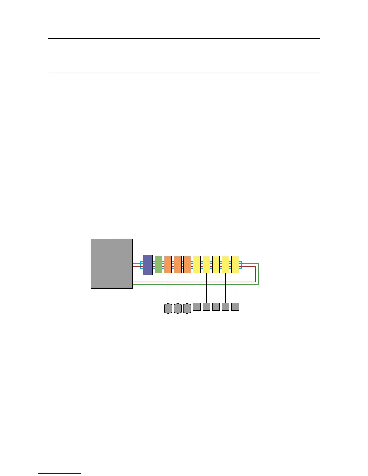
Fig 2.3 Touchpoint Pro Controller
Touchpoint Pro Controller
Communication
Board (COB)
Control Centre
Board (CCB)
Redundant Ring Network
PSU RCM Input Modules Output Modules
Ring A
Ring B
DIN Rail
Gas Detectors
Actuator Field Devices
The Ring Network is the communication link between all I/O modules in a Touchpoint Pro system and
the Control Centre Board. The Ring Network is the only connection required between a Touchpoint Pro
Controller (containing the Control Module and User Interface) and Remote Touchpoint Pro units.
The Ring Network is implemented for redundancy as two loops transmitting in opposite directions (Ring A
and Ring B). The network is self-healing since each module only communicates with the one next to it. If
a module fails, the modules after it continue to transmit data in the direction away from the failed module,
while the ones before it transmit in the other direction. Thus the Touchpoint Pro system can immediately
detect and locate a failed module, without affecting the availability of the rest of the system. For a single
Touchpoint Pro Controller, the Ring Network runs between the Communication / Power Rail and the Control
Module. For a system with a Touchpoint Pro Controller and Remote units, the network runs additionally over
data cable between all the units in a system.
Note: The Touchpoint Pro Ring Network does not accommodate spurs.

 Loading...


