MAN0923_Issue 3_04/15 Touchpoint Pro
Operating Instructions
180
14.2.3 Electrical connections
The electrical connections are shown below:
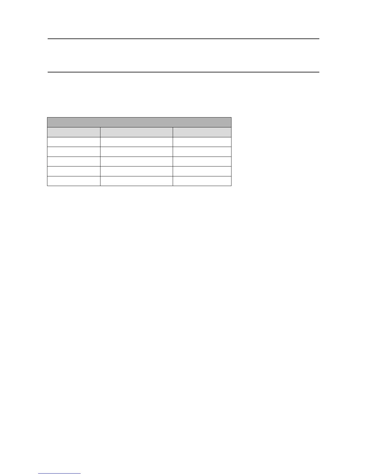
Modbus RTU Interface
Terminal TB6 TB7
1 A1 IN A2 IN
2 B1 IN B2 IN
3 A1 OUT A2 OUT
4 B1 OUT B2 OUT
5 Drain TB6 Drain TB7
Note: The respective IN and OUT terminals are connected together internally, i.e. A1 IN is connected to
A1 OUT
14.2.4 Conguration Examples
The Modbus interface consists of two independent Modbus ports. The RS485 connections are located on
terminals TB6 and TB7 of the Control Module. For convenience, IN and OUT terminals are provided which
are connected together internally.
Thediagrambelowgivesexamplecongurationsofwhichthesecondandthirdofferredundancy:
14.2.5 Termination resistor
If the Touchpoint Pro is the last node in a Modbus system highway, it is necessary to connect a termination
resistorbetweenAandB,toavoidreectionsontheRS485circuit.
For convenience, Touchpoint Pro has a set of jumpers which will switch a 120 Ω resistor across the
connection. In this case, the RS485 IN and OUT terminals are no longer connected together internally, and
theOUTterminalsareoating.OnlytheINterminalsshouldbeused.
Note: The default conguration for the jumpers is with the termination resistance off.
14. Appendix 1 - Modbus Option