MAN0923_Issue 3_04/15 Touchpoint Pro
Operating Instructions
63
4. Electrical Installation
Theauxiliaryvoltagesupplycanprovide18-32Vdc(24Vdcnominal)totheelddevicesatamaximum
current of 1.5 A per channel, with the additional limitation that the total current drawn from the module must
not exceed 1.5 A. The supply is short circuit protected – if a short circuit is detected the supply to all four
channels will be disconnected to prevent damage to the module. If the cause of the short circuit is removed,
the auxiliary voltage supply will be restored automatically.
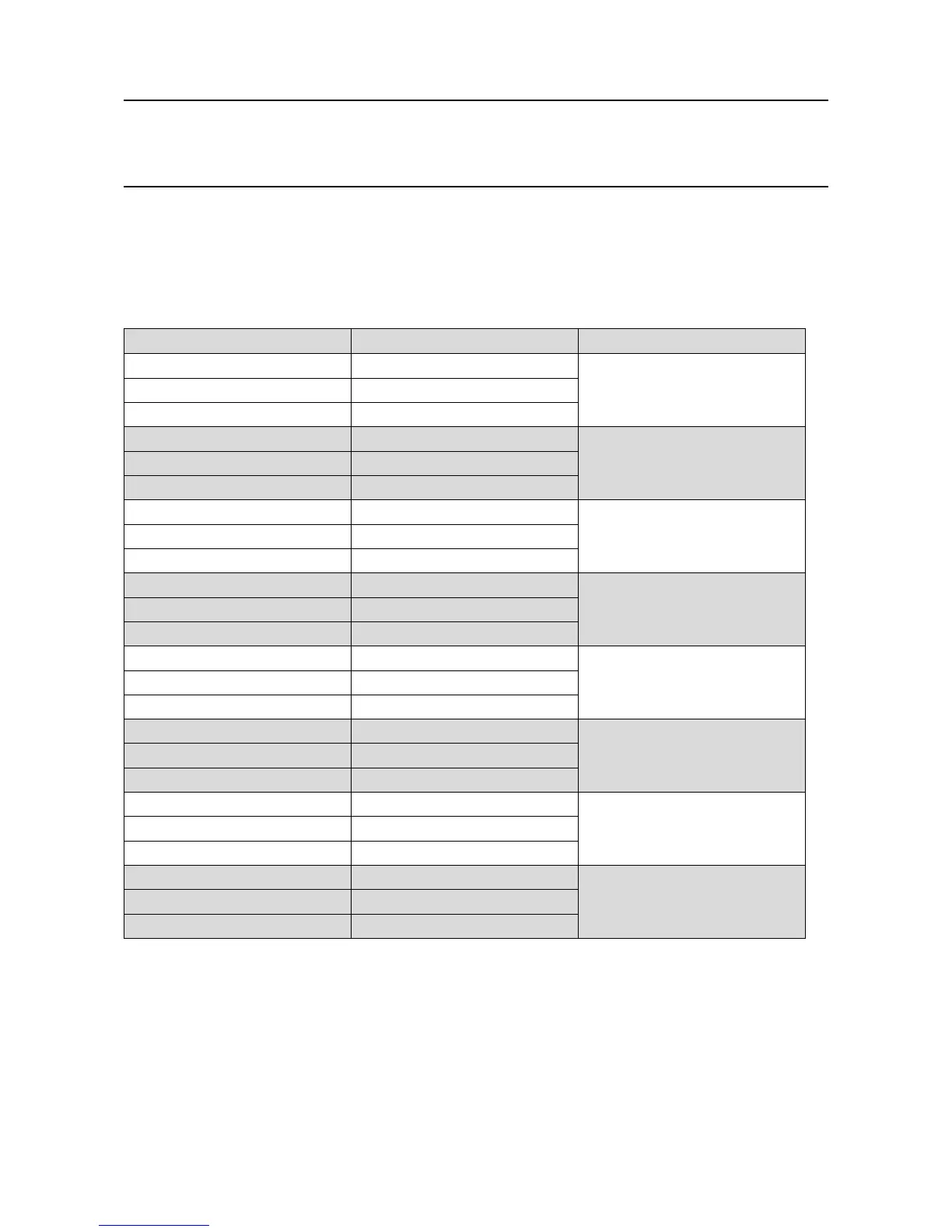
Terminal Identication Label Channel
1 NO Relay 1
2 NC
3 C
4 NO Relay 2
5 NC
6 C
7 NO Relay 3
8 NC
9 C
10 NO Relay 4
11 NC
12 C
13 V Aux 1
14 +V
15 -V
16 V Aux 2
17 +V
18 -V
19 V Aux 3
20 +V
21 -V
22 V Aux 4
23 +V
24 -V
Note: Relay contacts are shown in the shelf state (not powered)