Home
Honeywell
Control Systems
touchpoint Pro
Honeywell touchpoint Pro User Manual
4
of 1
of 1 rating
241 pages
Give review
Manual
Specs
To Next Page
To Next Page
To Previous Page
To Previous Page
Loading...
MAN0923_Issue 3_04/15
T
ouchpoint Pro
Operating Instructions
125
8. Maintenance
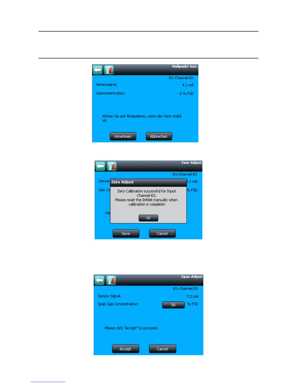
Figure 8.9 Zero Calibration Screen
7.
Conrm that the gas reading is zero, and press Save then OK
Figure 8.10 Zero Calibration Conrmation
8.
Select
Span Adjust
9.
Enter the concentration of the span gas and pr
ess
Accept
Figure 8.11 Enter Span Gas Concentration
124
126
Table of Contents
Default Chapter
2
Table of Contents
2
1 Safety and Information
8
How to Use this Manual
11
Safety Hazards
12
Location and Description of Warning Labels
14
Equipment Rating Labels (Hazardous Locations)
15
Disposal
16
Batteries
17
Information
18
2 Overview / Introduction
19
Touchpoint Pro Controller
20
System Topology
21
Input/Output (I/O) Modules
22
Available Modules
23
Sensor Catalogue
24
Power Supply Options
25
Touchpoint Pro UPS Module with Backup Battery
26
3 Mechanical Installation
27
Small Wall Mounted Enclosure – Mild Steel
29
Large Wall Mounted Enclosure – Mild Steel
30
Hazardous Area Enclosure
31
Floor Standing Enclosures
32
Floor Standing Cabinet - Front Access
33
Floor Standing Cabinet - Rear Access
35
Rack Mounted Unit
37
Touchpoint Pro Battery Box
39
Touchpoint Pro Battery Box Assembly
41
Cooling and Ventilation
43
4 Electrical Installation
44
DC Power Input
45
Ring Network
46
VDC Power - Controller
47
Earthing
48
EMC / RFI Considerations
50
Electrical Connections
51
Power Redundancy Module
54
UPS and Battery Box
55
Analogue Input Module 4-20 Ma
57
Analogue Input Module MV Bridge
60
Digital Input Module
61
Relay Output Module
62
Ring Coupling Module
64
Commission Power Supply Unit Status Channels
86
Buzzer Activation and Button Password Protection
87
Calibrate Touch Panel
88
Calibrate MV Input Channels
89
Calibrate Ma Input Channel Loops
90
7 Normal Operation
92
Navigation - Inputs and Outputs Screens
94
Navigation - Active Events
95
Overview – Web Server Interface
96
Navigation – Inputs and Outputs Screens
98
Navigation – Active Events
99
Alarms
100
Acknowledge an Active Alarm
101
Faults and Warnings
102
Reset a Latched Fault or Warning
103
View Input Channels and Input Details
104
View Output Channels
105
View Trend Graph
107
View Event History
108
Access Diagnostic Information
109
8 Maintenance
110
Field Inputs Test
111
Configuration Settings Test
112
Cause and Effect Test
113
Routine Maintenance
114
How to Replace a Faulty I/O Module
115
How to Remove or Decommission an I/O Module
120
Backup / Restore Configuration
122
Change the SD Card
123
Touchpoint Pro Battery Box
126
Routine Maintenance
128
9 Problem Solving
129
List of Error Codes
132
Further Assistance
143
10 Specifications
144
U Remote Unit Enclosure Without User Interface
145
Floor Standing Enclosures
147
Floor Standing Cabinets Front Access
148
DIN Rail (Module Supply and Communication)
149
Power Supply Redundancy Module (RDN Module)
150
Backup Batteries
151
Control Module and User Interface
152
Analogue Input Module MV Bridge
153
Digital Input Module
154
11 Certification
155
National and International Certificates
156
12 Ordering Information
158
Touchpoint Pro Control System Part Number Generator
160
TPPR-V Controllers and Remote Units
161
TPPR-H Enclosures
163
TPPR-W Psus
175
13 Honeywell Analytics Product Warranty
176
14 Appendix 1 - Modbus Option
177
Installation
178
Cable Recommendation
179
Electrical Connections
180
Multi-Drop Mode
184
Configuration
185
Register Allocation for Function 02 – Read Input Status
186
Register Allocation for Function 04 – Read Input Registers
187
Query Poll Registers
188
Query Types Available
189
Command Poll Registers
190
Exception Responses
191
15 Appendix 2 - Configurable Parameter Reference Guide
192
Sensor Settings
193
Suppression Settings
194
Threshold Alarm Hysteresis
195
Rate Alarm Settings 1
196
Inhibit Delay Settings
197
Gas Range Fault Settings
198
Calibration Signal Settings
199
Fault Signalling Settings 1
200
Analogue Input Module MV Bridge
201
Sensor Settings
202
Suppression Settings
203
Threshold Alarm Hysteresis
204
Inhibit Delay Settings
205
Calibration Reminder Settings
206
Digital Input Module
207
Alarm Settings
208
Relay Output Module
209
Cause and Effect Type Selection
210
16 Appendix 3 - Wiring Diagrams
211
AIM 4-20 Ma with 2 Wire Device Powered by AIM Ma
212
AIM 4-20 Ma with 3 Wire Device Powered by External Power Supply
213
AIM 4-20 Ma with 2 Wire Device Powered by External Power Supply
214
DIM in Unsupervised Configuration
215
DIM in Supervised Open Circuit Configuration
216
DIM in Supervised Configuration
217
AIM MV with Sensor Connectivity
218
ROM with Internal Auxiliary Supply in NC and no Configuration
219
ROM with External Auxiliary Supply in NC and no Configuration
220
17 Appendix 4 - Abbreviations
221
18 Appendix 5 - User Interface Software Menu Structure
222
19 Appendix 6 - Glossary of Icons
227
20 Appendix 7 - Logged Events and Where They Are Displayed
230
Other manuals for Honeywell touchpoint Pro
Technical Handbook
200 pages
Operating Manual
100 pages
Security Guide
12 pages
4
Based on 1 rating
Ask a question
Give review
Questions and Answers:
Need help?
Do you have a question about the Honeywell touchpoint Pro and is the answer not in the manual?
Ask a question
Honeywell touchpoint Pro Specifications
General
Brand
Honeywell
Model
touchpoint Pro
Category
Control Systems
Language
English
Related product manuals
Honeywell T8205B
12 pages
Honeywell TS8205A
12 pages
Honeywell Tema-Voyager Compact
65 pages
Honeywell Touchpoint 4
18 pages
Honeywell Touchpoint Plus
70 pages
Honeywell XLS80e
138 pages
Honeywell VR8304
14 pages
Honeywell RP-2002
1 page
Honeywell Excel 500
48 pages
Honeywell Experion LX
331 pages
Honeywell vk41 series
34 pages
Honeywell ComfortPoint Open
16 pages