464
S:\HP892XX\USRGUIDE\manual\radscrn.fb
Chapter 16, Radio Interface Screen
Using the Radio Interface (Manual Operation)
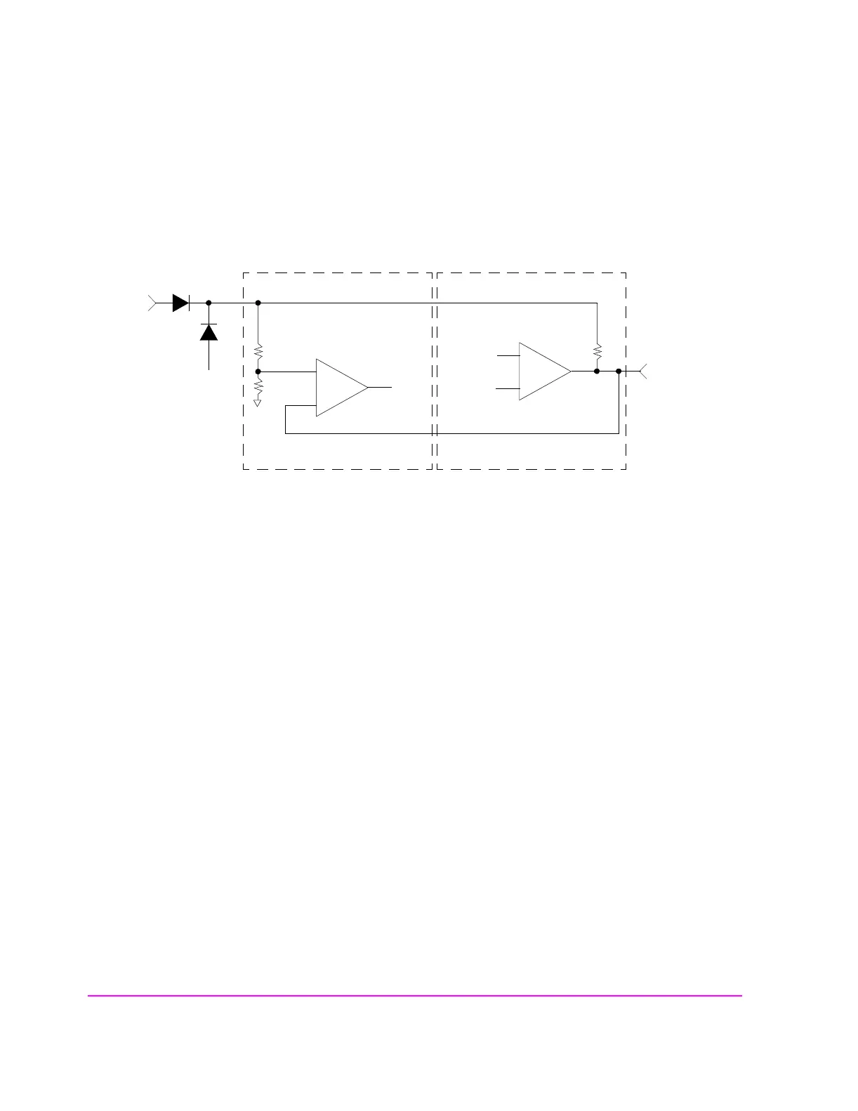
Figure 118
For data input, use the following formula to determine the logic threshold voltage:
(Logic Voltage
− 0.7) × 0.34 = V
threshold
For example, the default Logic Voltage of 5.1 V would give:
4.4
× 0.34 = 1.5 V
A 12.5 V supply connected to the Logic Voltage pin 9 would give:
11.8
× 0.34 = 4 V
For data output, calculate the logic high level using this formula:
Logic Voltage
− 0.7 through a 3.16 k ohm pull-up resistor.
A logic low on the data output will be near 0 V, depending on the amount of
current the comparator is sinking. For example, if the output current is 4 mA, the
output voltage will be about 250 mV.
+
-
+
-
31.6 k
56.2 k
LM 339M
5.1 V
Default Logic
Voltage
Pin 9 Logic
Voltage
Input
Data
Output Data
Fixed Ref-
erence
3.16 k
LM 339M
Pins 19-34
Parallel
Data Out
Input Data Line (1 of 16) Output Data Line (1 of 16)