573
Chapter 24, Connector, Key, and Knob Descriptions
Connector Descriptions
RADIO INTERFACE
This connector is optional on all Test Sets.
This connector provides parallel communications between the Test Set and
external radio equipment. The connector provides a 16-line parallel digital
interface that you can configure as inputs, outputs, or a combination of inputs and
outputs. You can set the logic thresholds and output levels so that the interface
will match the levels and thresholds of the device it is connector to. Audio and
transmitter control lines are also provided.
Parallel communication parameters are entered in the RADIO INTERFACE
screen. This screen is only available if the Radio Interface option is installed.
The audio signal from this connector is input by setting the
AF Anl In field to
Radio Int. (The AF Anl In field is available in the TX TEST, DUPLEX
TEST, and AF ANALYZER screens, as well as various DECODER screens.)
Radio Interface Operating Considerations
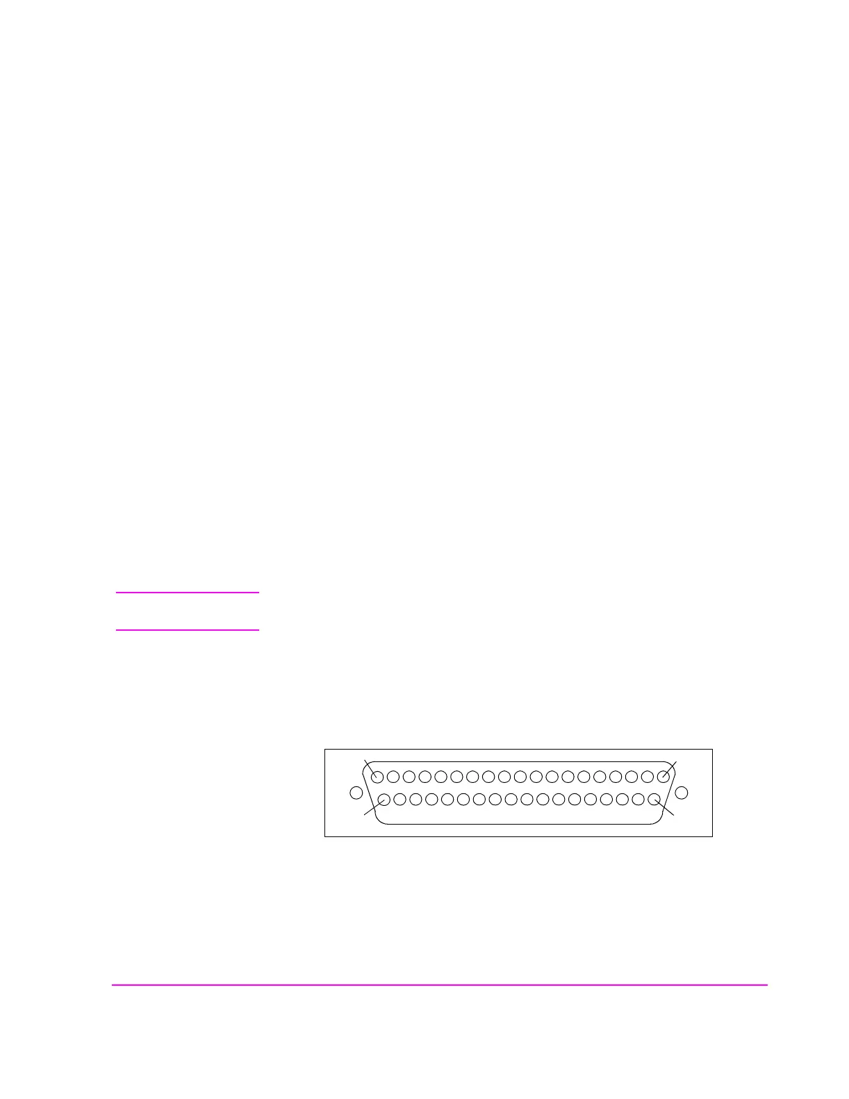
Connector type: D-Subminiature, 37 pin.
All pins have 4.6
µH chokes in series for RFI suppression. Control and data lines
have clamp diodes across them for electrostatic discharge protection.
CAUTION: To prevent damage to the diodes, the input voltage must not exceed logic voltage +0.6 V or be
less than −0.6 V.
Rise times are affected by capacitive loading. This is because the control and data
lines have 3.16 k
Ω pull-up resistors.
Fall times are affected by open collector current sink limitations.
Figure 147 Pin Numbers for the Radio Interface Connector
19
1
20
37