379
3. Create a GRE tunnel:
a. Select VPN > GRE from the navigation tree.
b. Click Add.
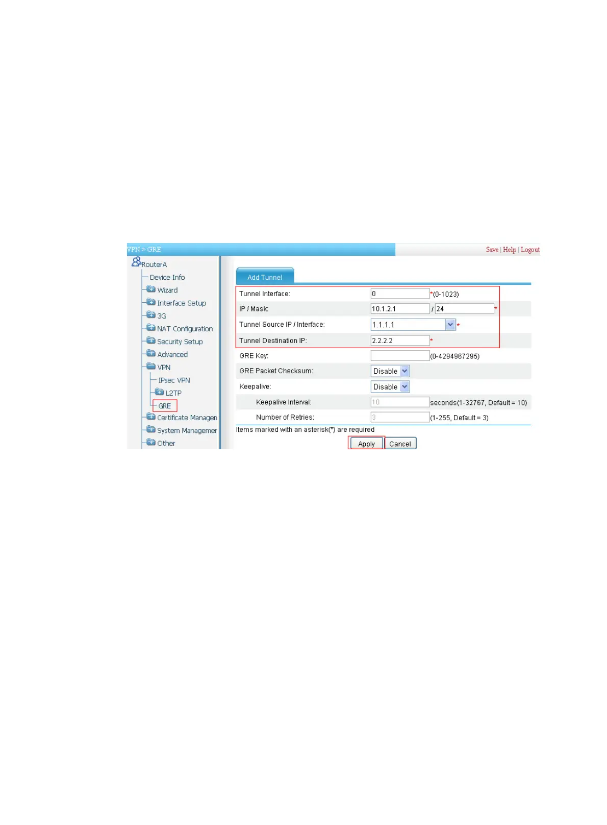
The Add Tunnel page appears, as shown in Figure 381.
c. Enter 0 in the Tunnel Interfa
ce field.
d. Enter IP address/mask 10.1.2.1/24.
e. Enter the source end IP address 1.1.1.1, the IP address of Ethernet 0/1.
f. Enter the destination end IP address 2.2.2.2, the IP address of Ethernet 0/1 on Router B.
g. Click Apply.
Figure 381 Setting up a GRE tunnel
4. Configure a static route from Router A through interface Tunnel0 to Group 2:
a. Select Advanced > Route Setup from the navigation tree.
b. Click the Create tab and then perform the configurations shown in Figure 382.
c. Enter 10.1.
3.0 as the destination IP address.
d. Enter mask 24.
e. Select the box before Interface, and then select egress interface Tunnel0.
f. Click Apply.

 Loading...


