3 - 29
PN 074-550-P1C
SQC-310 Operating Manual
Editable Input parameters are:
Name: A logical name for this input. The system-defined default name can be
returned by pressing the Set to Default button.
Active Level: The level, high (5 V) or low (0 V) that triggers the input.
Input Number: The physical input assigned to this logical input function.
Allows for reassignment of inputs without physically rewiring any inputs
or connectors.
Editable Relay parameters are:
Name: A logical name for this relay. The system-defined default name can be
returned by pressing the Set to Default button.
Type: Normally Open (NO) contacts or Normally Closed (NC) contacts.
SQC-310 uses software to implement the NO/NC function. All relays are
normally open and will open when SQC-310 is not powered.
Pulses: Number of pulses required for activation. Setting Pulses to One Pulse
will cause the relay to turn on for the Pulse Width amount of time, then turn off.
Selecting None causes the relay to activate when the logical relay function is
true, and deactivate when it is not. If a multi-crystal sensor is used and Control
Type is set to Direct (see section 3.12.3.1 on page 3-36), this setting is
read-only for any sensor drive relays.
Pulse Width: The time (in seconds) that the relay activates if One Pulse or Two
Pulses is selected.
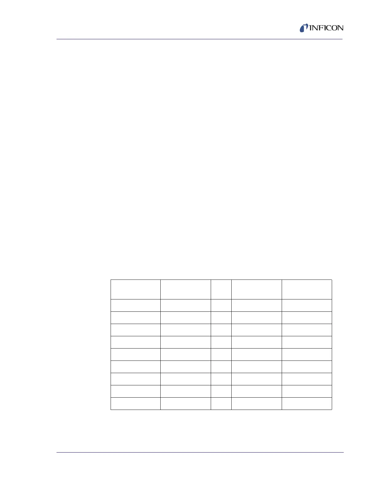
Relay Number: The physical output assigned to this logical relay function.
This allows for reassignment of relays without physically rewiring any relays or
connectors. Connector pins for these assignments are displayed in Table 3-11.
NOTE: Relays 9 to 16 and inputs 9 to 16 use the same connector pins as found
on the second rear panel I/O connector (if available) in the same
sequential order.
Table 3-11 Relay and Input connector pin assignments
Relay
Number
Connector
Pins
Input
Number
Connector
Pin
Relay 1 14,15 Input 1 16
Relay 2 1,2 Input 2 17
Relay 3 3,4 Input 3 18
Relay 4 5,6 Input 4 19
Relay 5 7,8 Input 5 20
Relay 6 9,10 Input 6 21
Relay 7 11,12 Input 7 22
Relay 8 13,25 Input 8 23
Ground 24