AFI value of 2 (IPv6) and a SAFI value of 1 (unicast). As the next hop in the
MP-REACH-NLRI attribute, CE 1 advertises the IPv6 address of the CE 1 interface that
links to PE 1.
Both IPv4 and IPv6 addresses must be configured on the PE-CE link. The IPv6 address
defaults to an IPv4-compatible address that can be overridden with policy.
PE 1 and PE 2 establish an MP-BGP session using their remote loopback IPv4 addresses
as neighbor addresses. Router PE 1 installs in its IPv6 global routing table the route
advertised by CE 1. MP-BGP on PE 1 then binds a second-level label, L2, and advertises
the route to PE 2 with an AFI value of 2 (IPv6) and a SAFI value of 4 (labeled routes).
The next hop that PE 1 advertises in the MP-REACH-NLRI attribute is the IPv4 address
of its loopback interface, 10.1.1.1, encoded in IPv6 format as ::10.1.1.1.
When MP-BGP on router PE 2 receives the advertisement, it associates the base tunnel
(to 10.1.1.0/24, label L1) with the next hop (::10.1.1.1) that was advertised by PE 1 to reach
the customer IPv6 island, 2001:0430::/32. Router PE 2 then uses MP-BGP (AFI = 2, SAFI
= 1) to advertise to CE 2 its ability to reach this network.
CE 2 sends native IPv6 packets destined for the 2001:0430::/32 network to PE 2. On
receipt, PE 2 performs a lookup in its global IPv6 routing table. PE 2 prepends two labels
to the IPv6 header (L1–L2–IPv6) and then forwards the packet out its core-facing interface
(10.2.2.2).
The P router does a lookup on L1 and label switches the packet toward PE 1. The P router
can either replace L1 with another label or pop L1 if PE 1 requested PHP.
When PE 1 receives the packet on its core-facing interface, it pops all the labels and does
a lookup in the global IPv6 routing table using the destination address in the IPv6 header.
PE 1 then forwards the native IPv6 packet out to CE 1 on the IPv6 link.
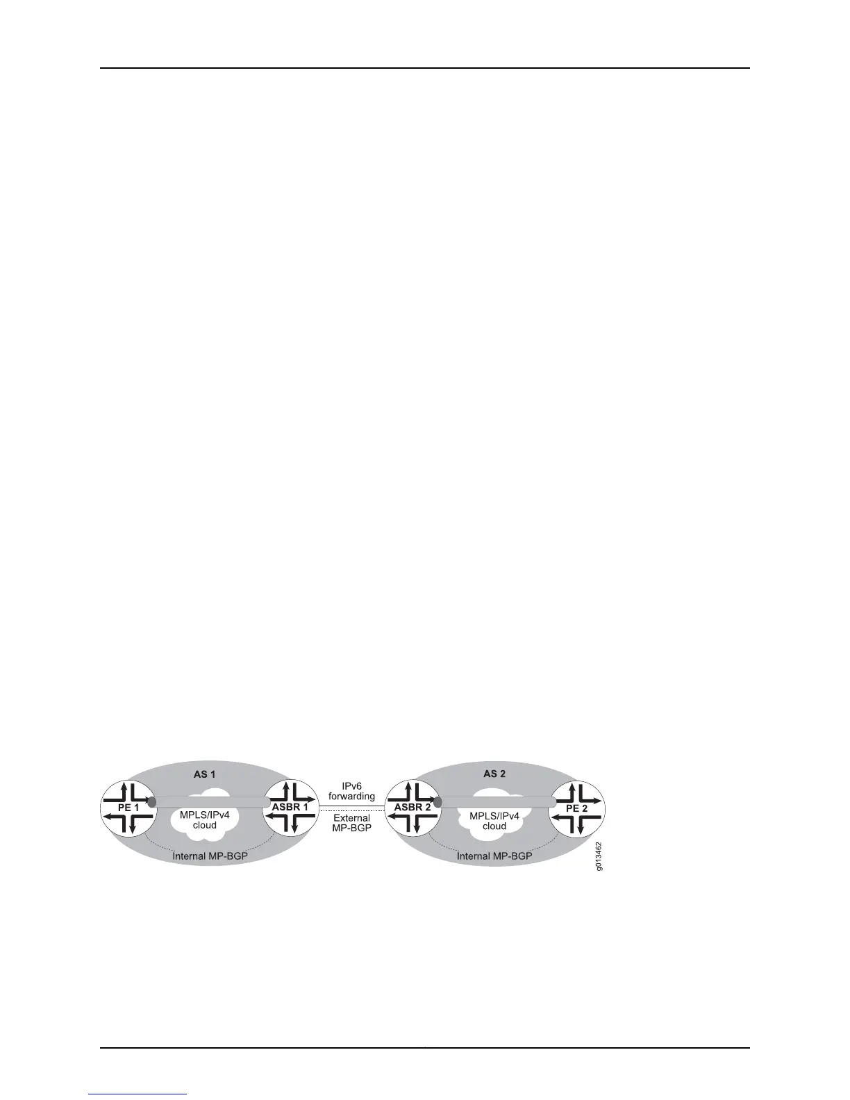
Connecting IPv6 Islands Across Multiple IPv4 Domains
When the IPv6 islands are separated by multiple IPv4 domains, the autonomous system
boundary routers between the IPv4 domains must be DS-BGP routers (Figure 111 on
page 477).
Figure 111: IPv6 Tunneled Across IPv4 Domains
Each of these AS boundary routers establishes a peer relationship with the DS-BGP
routers in its own domain, creating a separate mesh of tunnels among the DS-BGP routers
of each domain. Routing between PE 1–ASBR 1 in AS 1 and between PE 2–ASBR 2 in AS
2 is accomplished by means of label-switched paths.
477Copyright © 2010, Juniper Networks, Inc.
Chapter 6: Configuring BGP-MPLS Applications
 Loading...