•
LDP signaling—VPLS with LDP signaling, which is referred to as LDP-based VPLS, uses
LDP as the protocol that signals reachability for the VPLS domain in which the VPLS
instance participates. You must configure LDP on each PE router in your topology to
provide signaling for each VPLS domain.
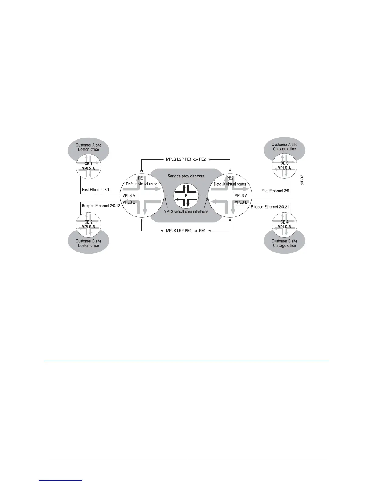
Figure 128 on page 574 illustrates an example of a simple VPLS topology. The basic
topology of a VPLS network is the same regardless of whether BGP signaling or LDP
signaling is used.
Figure 128: VPLS Sample Topology
Related Topics BGP Signaling for VPLS Overview on page 579•
• Configuring VPLS with BGP Signaling on a PE Router on page 590 in Configuring VPLS
on page 589
• LDP Signaling for VPLS Overview on page 580
• Configuring VPLS with LDP Signaling on a PE Router on page 602 in Configuring VPLS
on page 589
• Configuring BGP-MPLS Applications on page 383
• Configuring VPWS on page 651
VPLS Components Overview
As illustrated in Figure 128 on page 574, a typical VPLS topology consists of the following
components.
•
VPLS Domains on page 575
•
Customer Edge Devices on page 575
•
VPLS Edge Devices on page 575
Copyright © 2010, Juniper Networks, Inc.574
JunosE 11.2.x BGP and MPLS Configuration Guide
 Loading...