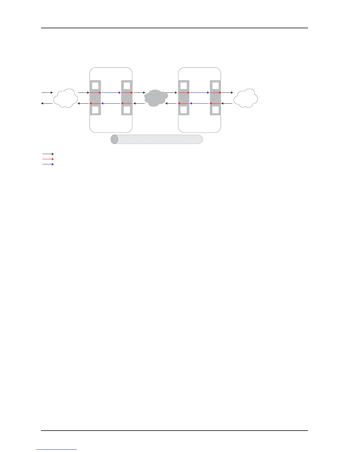
Figure 125: Ethernet Packet Distribution over Martini Circuits
MPLS network
g016509
A
D
B
C
RT1
RT2
MPLS Edge Router 1
PE1
Line
module
Line
module
MPLS tunnel
Layer 2 services
C
B
D
A
RT2
RT1
MPLS Edge Router 2
PE2
Line
module
Line
module
Layer 2 services
External network connections
Internal forwarding paths
Router-fabric traversal
Consider a scenario in which Ethernet raw mode is not enabled on the S-VLAN
subinterface of the PE-facing devices. When a packet reaches the S-VLAN subinterface
on an ingress line module, point A, inside PE1, all packets, regardless of whether they are
tagged or not, are forwarded to the subinterface on the egress line module, B, inside PE1
without any change. This behavior applies to both ES2 4G LMs, ES2 10G LMs, ES2 10G
Uplink LMs, and ES2 10G ADV LMs. At point B, the MPLS encapsulation header is added
to the packet and the egress line module forwards it to the MPLS network. This
functionality is the same for both ES2 4G, ES2 10G, ES2 10G Uplink, and ES2 10G ADV
LMs. When the packet reaches the subinterface on the ingress line module (ES2 4G LM
and ES2 10G LM), point C, inside PE2, the added MPLS header is removed and the packet
is sent to the subinterface on the egress line module, point D, for further processing. At
point D, for ES2 4G LMs, the packet is sent to the remote CE-facing device, depending
on the configuration of the S-VLAN subinterface. If the packet arrives with a single or no
tag, the router adds the S-VLAN tag and sends it to the CE-facing device. On ES2 10G
LMs, ES2 10G Uplink LMs, and ES2 10G ADV LMs, at point D, the packet is forwarded to
the CE-facing device without any modification.
In the same scenario, when Ethernet raw mode is enabled on the S-VLAN subinterface
of the PE devices, the processing of Ethernet packets is performed in a slightly different
way. At the S-VLAN subinterface on an ingress ES2 4G LM, ES2 10G LM, ES2 10G Uplink
LM, and ES2 10G ADV LM, point A, inside PE1, the S-VLAN tag is removed from the received
packet before being forwarded to the subinterface on the egress line module, B, inside
PE1. At point B, the MPLS encapsulation header is added to the packet and the egress
line module forwards it to the MPLS network. This functionality is the same for both ES2
4G LMs ,ES2 10G LMs, ES2 10G Uplink LMs, and ES2 10G ADV LMs. When the packet
reaches the subinterface on the ingress ES2 4G LMs, ES2 10G LMs, ES2 10G Uplink LMs,
and ES2 10G ADV LMs, point C, inside PE2, the added MPLS header is removed and the
packet is sent to the subinterface on the egress line module, point D, for further processing.
This behavior is the same, regardless of whether raw mode encapsulation is enabled or
not. At point D, for both ES2 4G LMs, ES2 10G LMs, ES2 10G Uplink LMs, and ES2 10G
ADV LMs, the S-VLAN tag is inserted into the packet and sent to the CE-facing device at
the remote site.
Copyright © 2010, Juniper Networks, Inc.556
JunosE 11.2.x BGP and MPLS Configuration Guide
 Loading...