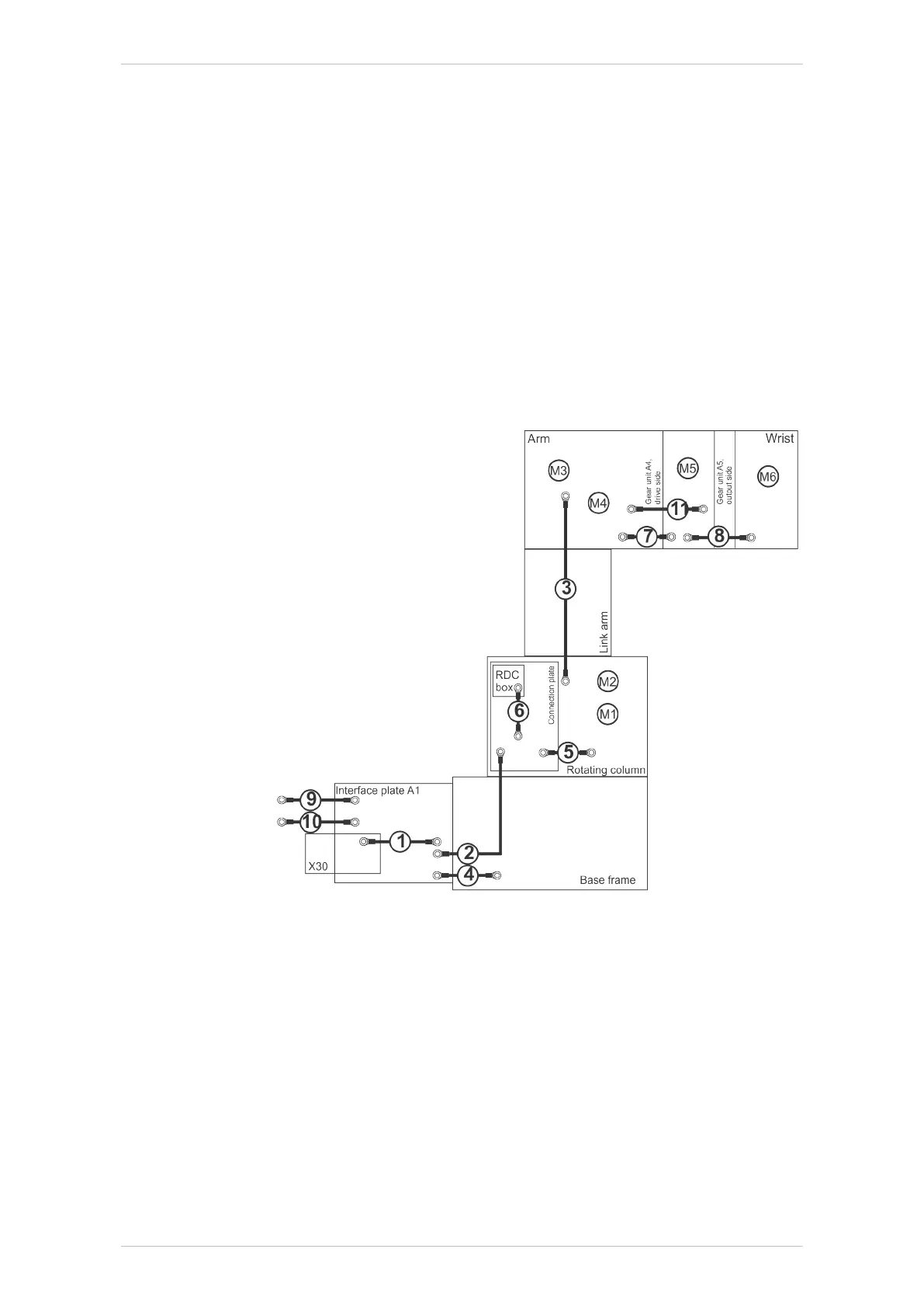
4 Ground conductor, interface plate A1 – base frame
Cross-section: 4 mm
2
5 Ground conductor, connection plate – rotating column
Cross-section: 4 mm
2
6 Ground conductor, RDC box – connection plate
Cross-section: 4 mm
2
7 Ground conductor, arm – wrist
Cross-section: 4 mm
2
8 External ground conductor / system potential
Cross-section: 16 mm
2
9 External ground conductor (KRC)
Cross-section: 16 mm
2
11 Ground conductor, arm – wrist main body
Cross-section: 1.5 mm
2
Fig. 9-68: Wiring diagram, protective circuit, KR 30/50/70 R2100 and
KR 50 R2500
1 Ground conductor, interface plate A1 – holding plate
Cross-section: 4 mm
2
2 Ground conductor, connection plate and RDC box
Cross-section: 4 mm
2
3 Ground conductor, rotating column – arm
Cross-section: 4 mm
2
4 Ground conductor, interface plate A1 – base frame
Cross-section: 4 mm
2
5 Ground conductor, connection plate – rotating column
Cross-section: 4 mm
2
KR IONTEC
308/344 | www.kuka.com MA KR IONTEC V4 | Issued: 11.05.2021
Repair

 Loading...

