Maximum supplementary load, arm 30 kg
Load center of gravity and mass moment of inertia
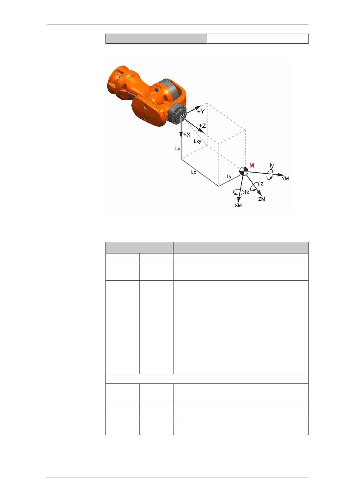
Fig. 4-5: Load center of gravity and mass moment of inertia
Parameter
Parameter/unit Description
Mass kg Payload mass
L
x
, L
y
, L
z
mm Position of the center of mass in the reference
system
A, B, C Degrees Orientation of the principal inertia axes
• A: Rotation about the Z axis of the refer-
ence system
The result is a coordinate system named
CS'.
• B: Rotation about the Y axis of CS'
Result: CS''
• C: Rotation about the X axis of CS''
Note: A, B and C are not shown in the dia-
gram.
Mass moments of inertia:
I
x
kgm
2
Inertia about the X axis of the main axis sys-
tem
I
y
kgm
2
Inertia about the Y axis of the main axis sys-
tem
I
z
kgm
2
Inertia about the Z axis of the main axis sys-
tem
L
x
, L
y
, L
z
and A, B, C unambiguously define the main axis system:
• The origin of the main axis system is the center of mass.
KR IONTEC
40/344 | www.kuka.com MA KR IONTEC V4 | Issued: 11.05.2021
Technical data

 Loading...

