• A characteristic feature of the main axis system is that, among other
things, the maximum possible inertia occurs about one of the 3 coordi-
nate axes.
More information is contained in the KUKA.Load documentation.
Payload diagram
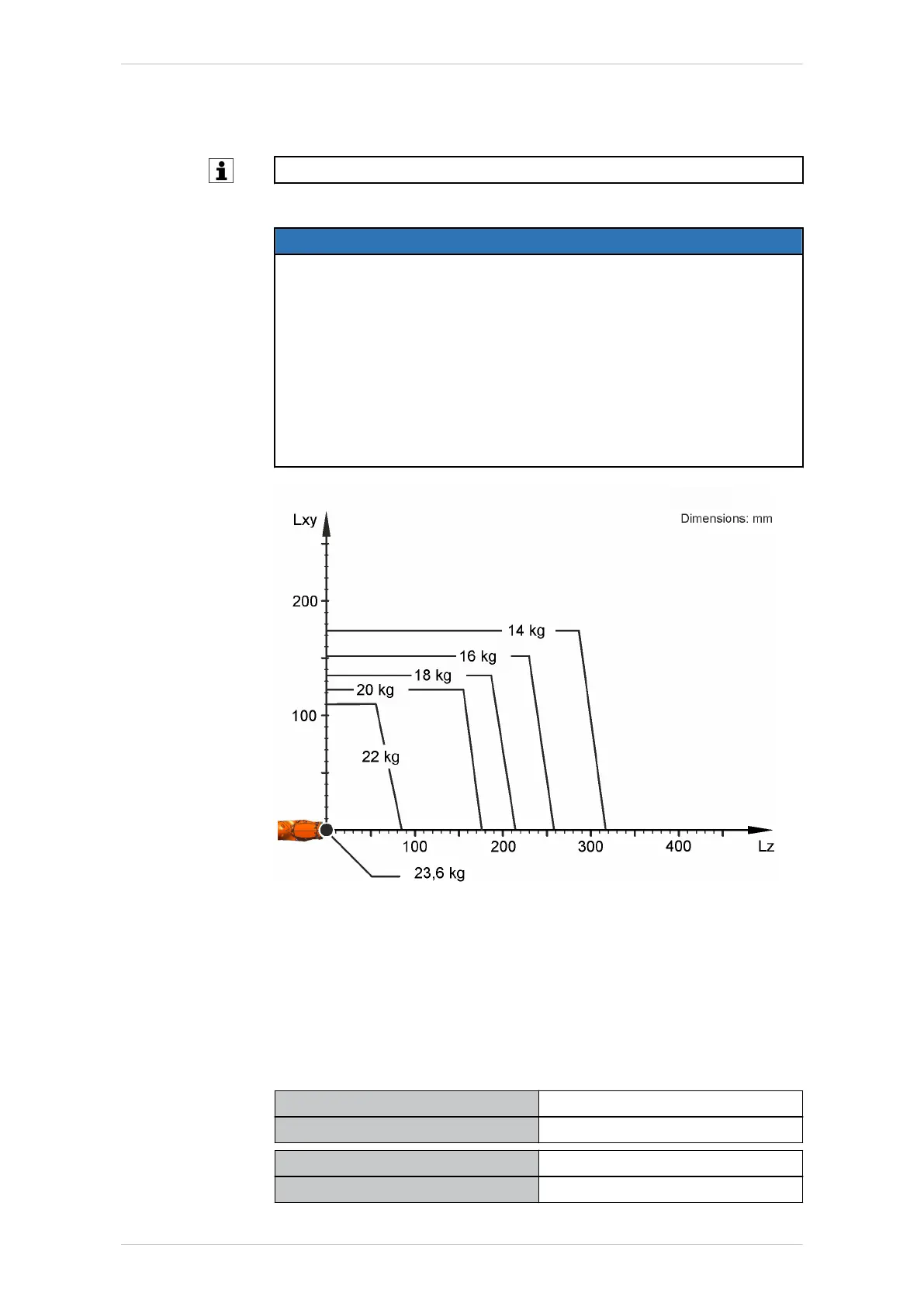
NOTICE
This loading curve corresponds to the maximum load capacity. Both val-
ues (payload and mass moment of inertia) must be checked in all ca-
ses. Exceeding this capacity will reduce the service life of the robot and
overload the motors and the gears; in any such case KUKA Deutsch-
land GmbH must be consulted beforehand.
The values determined here are necessary for planning the robot appli-
cation. For commissioning the robot, additional input data are required
in accordance with the operating and programming instructions of the
KUKA System Software.
The mass inertia must be verified using KUKA.Load or KUKA Compose.
It is imperative for the load data to be entered in the robot controller!
Fig. 4-6: KR 20 R3100, payload diagram
The KR 20 R3100 is designed for a rated payload of 20 kg in order to op-
timize the dynamic performance of the robot. The maximum payload of
23.6 kg applies only if the position of the center of mass is 0 mm and a
supplementary load optimized for the load case is mounted. The specific
load case must be verified using KUKA.Load or KUKA Compose. For fur-
ther consultation, please contact KUKA Support.
Mounting flange D=50
Robot wrist type ZH16/22
Mounting flange see drawing
Mounting flange (hole circle) 50 mm
Screw grade 12.9
KR IONTEC
MA KR IONTEC V4 | Issued: 11.05.2021 www.kuka.com | 41/344
Technical data

 Loading...

