C.5 GS18
Some applications require knowledge of the pin assignments for the instru-
ment p
orts.
In this chapter, the pin assignments and sockets for the instrument ports are
explained.
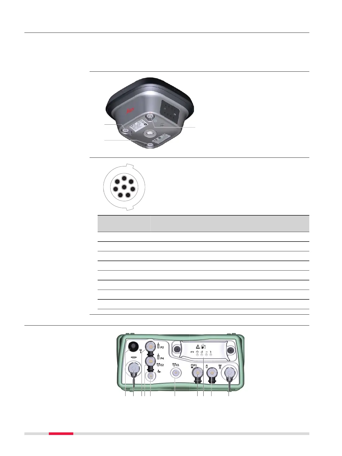
a SMB-connector for external
UHF an
tenna, only for models
with UHF radio
b SMB-connector for external
LTE antenna
c Port 1 (Power, USB and serial)
Pin Signal
Name
F
unction Direction
1 USB_D+ USB data line In or out
2 USB_D- USB data line In or out
3 GND Signal ground -
4 RxD RS232, receive data In
5 TxD RS232, transmit data Out
6 ID Identification pin In or out
7 PWR Power input, 10.5 V-28 V In
8 GPIO RS232, general-purpose signal In or out
C.6 GS25
Description
Ports at the instru-
men
t underside
Pin assignments for
po
rt P1
Ports at the instru-
ment back panel
1002 Pin Assignments




 To Next Page