Refer to "Segment Info - Start Point/Segment Info - End Point,Hz alignment
page" f
or a description of keys.
If a value has not been defined, the field is shown as -----.
Description of fields
Field Option Description
Line name Display only The name of the selected line.
Chainage Display only The chainage of start/end point of the seg-
ment.
Eas
ting,
Northing
and
Height
Display only The East/North coordinate and height of the
start/end point of the segment.
Grade Display only The grade at the start/end point of the seg-
ment.
Vertical
radius
Display only The radius at the start/end point of the seg-
ment.
Vertical
type
Display only The current segment type.
Next step
OK re
turns to the previous panel.
43.3 Configuring Roads Apps
43.3.1 Configuration Settings
Select one of the Road apps from the Leic
a Cap
tivate - Home menu.
In the Task press Fn Settings.
Description
E
sp
ecially when checking points in an as-built control or when staking out it is
useful to enable the Quality control criteria available. For every point stored,
the chosen parameters are checked and if the check limits are exceeded a
warning is shown. This function guarantees a higher productivity as it is no
longer necessary to check the values for every shot taken. Checking layers of a
road, a layer that is too thick results in higher costs as more material is used.
Alternatively, a too thin layer can lead to problems and could cause serious
damage. Therefore different check limits for above and below the design can
be defined.
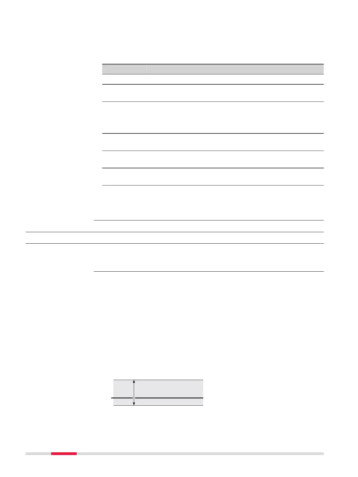
Graphic
a Layer is too thick
b Design surface
c Layer is too thin
d Upper height limit
e Lower height limit
Segment Info - Start
Poin
t/
Segment Info - End
Point,
Vertical alignment
page
Access
Road Settings,
Quality contr
ol page
628 Roads - General