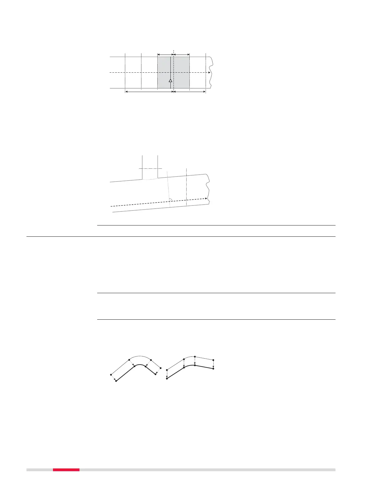
Measuring tunnel profiles - Plan view
a Centreline
b Ins
trument position
c Tunnel face
d Defined profile to scan
e Instrument profile
f Back distance
g Forward distance
h Back interval
i Forward interval
Profile view
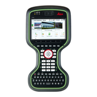
Tunnel p
rofiles can be measured vertically, horizontally or perpendicular to the
tunnel centreline.
a Centreline
b
T
unnel face
c Horizontal profile
d Profile perpendicular to cen-
treline
e Vertical profile
43.6.15 Tunnel - Shifts
When working on site, often design data does not match the measured data.
Fo
r example, an existing road surface that should intersect with the design sur-
face may be 15 cm higher than the plans indicate. For a smooth intersection,
this difference is distributed over the remaining 100 m of paving. To handle
these situations, the app allows the possibility of adding shifts to the existing
design data. A shift is applied when selecting the element to stake out/check.
Shifts do not change the stored design. They are applied temporarily for stake
out pur
poses.
Horizontal and vertical shifts
Ho
rizontal shifts are always perpendicular to the centreline whereas vertical
shifts are applied along the plumb line.
a Horizontal alignment with
co
nstant shift (plan view)
b Vertical alignment with con-
stant shift (profile view)
Constant and linear shifts are supported
Fo
r both horizontal and vertical shifts, two different types can be applied:
Constant: The shift remains the same from its start chainage or station
to the end chainage o
r station.
Description
☞
Centreline shifts
702 Roads - General



 To Next Page