4-136 Service Manual
5062
Installation notes:
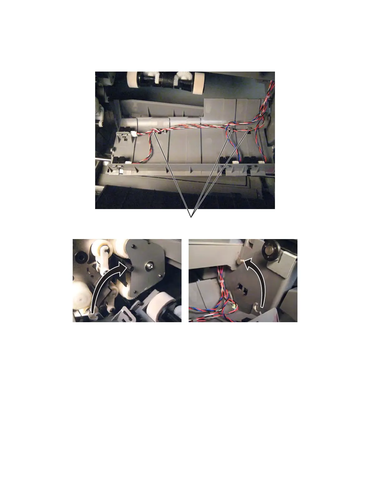
• Be sure the cables are routed through the cable hooks (B) before you snap the assembly into place. Use
the cable lengths as a guide to make sure you connect the correct cable to each sensor.
• Be sure the hooks engage both the bottom and top posts on each side.
Staging paper path reference edge assembly removal
See “Front” on page 7-7 for the part number.
1. Remove the rear cover. See “Rear cover removal” on page 4-18.
2. Remove the left cover. See “Left cover removal” on page 4-10.
3. Remove the paper pick mechanism. See “Paper pick mechanism assembly removal” on page 4-116.
4. Remove the fuser. See “Fuser assembly removal” on page 4-58.
5. Remove the ITU assembly. See “ITU assembly removal” on page 4-72.