HYDRAULIC AND AIR SYSTEMS 2250 SERVICE/MAINTENANCE MANUAL
2-22
Published 07-19-16, Control # 249-01
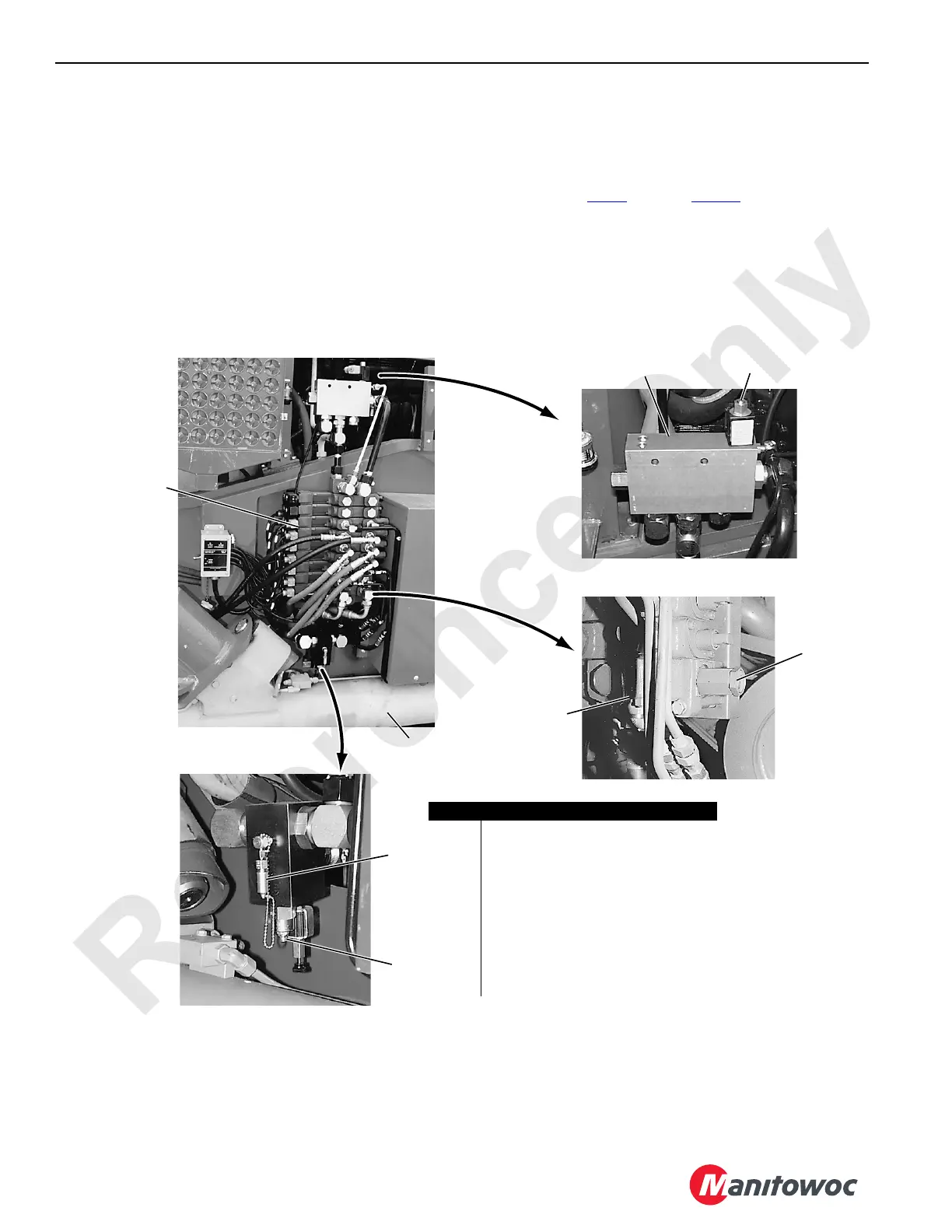
3. At the main relief valve (6) on the auxiliary system
control valve (5), loosen the lock nut and turn the
adjusting screw in one full turn. Securely tighten the lock
nut.
4. Start and run the engine at 1,500 rpm.
5. Fully retract both gantry cylinders until they bottom out
(stall the hydraulic system). Gauge pressure should be
241 to 248 bar (3,500 to 3,600 psi).
6. If the specified pressure is not indicated, proceed as
follows.
a. Loosen the lock nut on the adjusting screw for the
auxiliary system relief valve.
b. Turn the adjusting screw in to increase or out to
decrease the pressure.
c. Repeat step 5
through step 6b until the specified
pressure is obtained, and securely tighten the lock
nut.
7. Stop the engine and remove the gauge from the coupler
on the auxiliary system relief valve. Install a protective
cap over the coupler.
FIGURE 2-26
P923
P975
P922
P974
View C
View B
View A
Access at Right Rear
Corner of Rotating Bed
Item Description
1 Auxiliary System Valve Assembly
2 Jacking Cylinder (qty 4)
3 Proportional Flow Control Valve
4 Bleed Screw
5 Auxiliary System Control Valve
6 Main Relief Valve
(with lock nut and adjusting screw)
7 Gauge Coupler
8 Auxiliary System Relief Valve
(with lock nut and adjusting screw)
1
2
3
4
5
6
7
8
 Loading...


