Page 27Alterations reserved Stand 12/2002
Operating Manual
T 700 / T 800.1 - FP ENG
Continuation
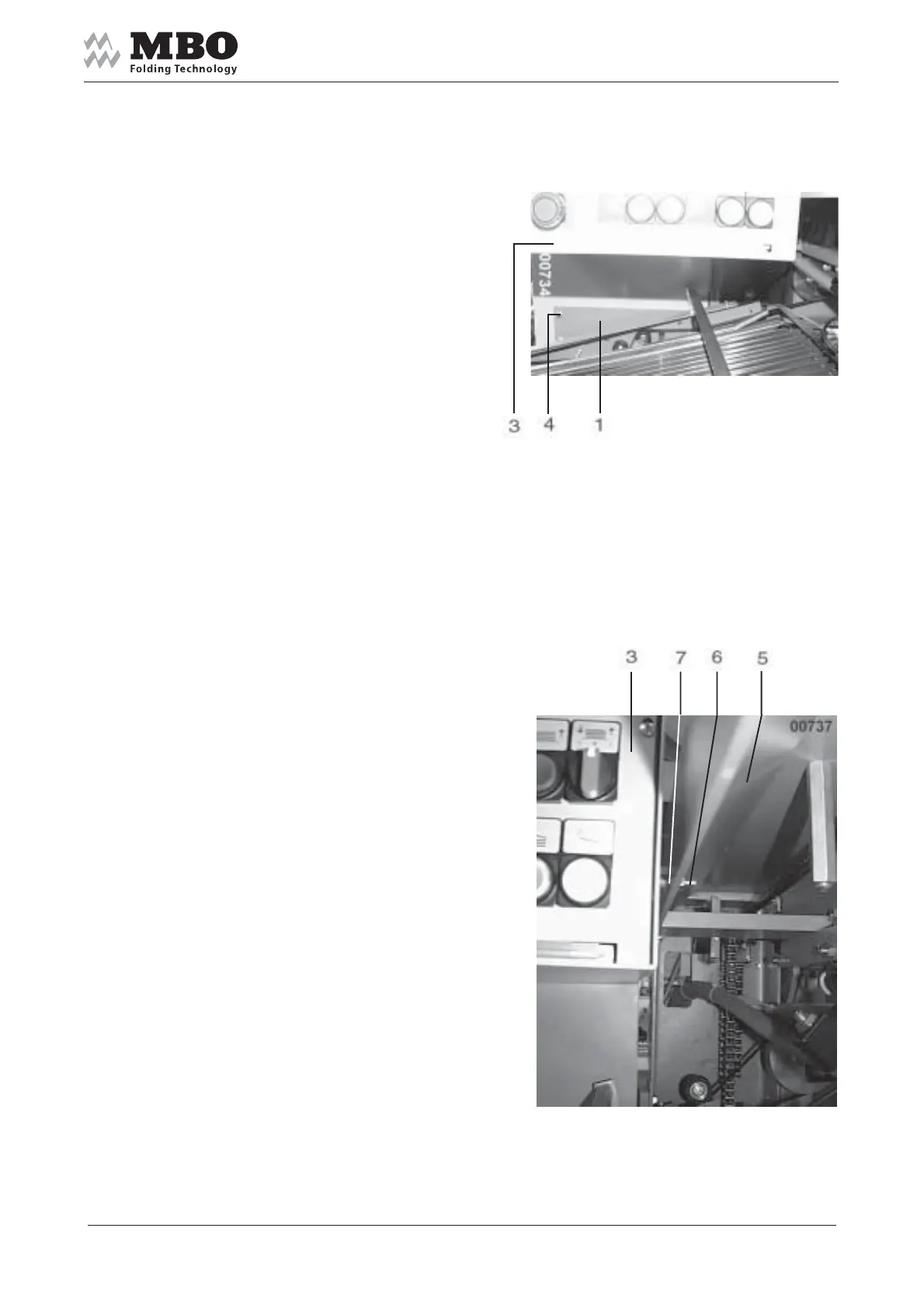
Then affix 4 the main control panel 3
onto holder 1.
3 to be affixed 6 at bar 5,
distance piece 7 between 3 and 5.
Insert the plugs of machine
and feeder into the corresponding
sockets at the control panel.
Matching plugs and sockets
bear the same marking.
Connect the cables of motors directly
with the motor protective switches
at main control panel.
Connect the pressure-/vacuum pump -
cables are numbered.
Please note wiring diagram!