Page 62
Alterations reserved Stand 12/2002
Operating Manual T 700 / T 800.1 - R ENG
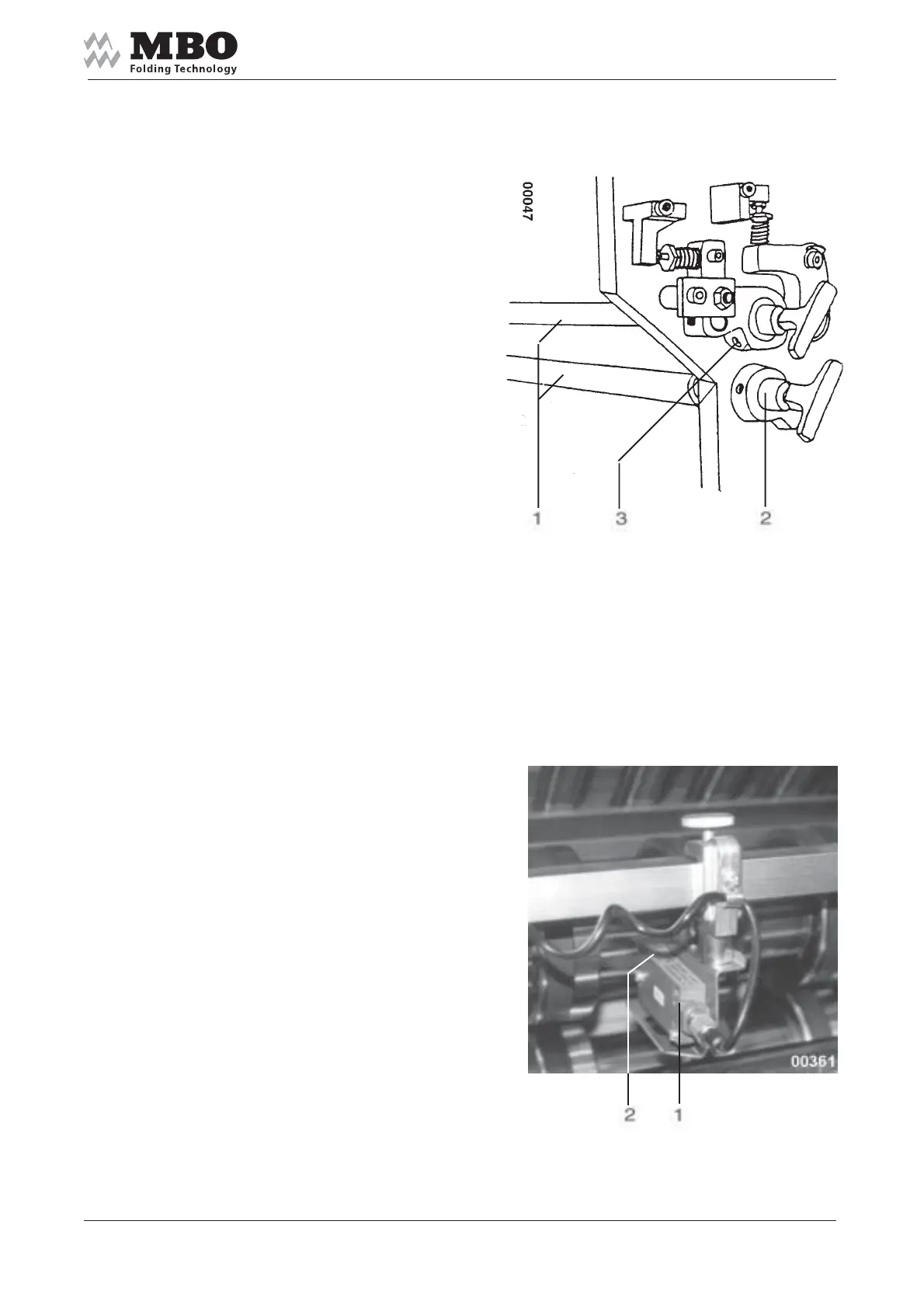
5.5.4 Slitter shafts
Each folding unit is equipped
with two slitter shafts 1 to enable
the insertion of tools for perforation,
scoring or cutting.
They can easily be mounted
and removed by plug bearings 2.
For that purpose loosen the screw 3
and pull out the plug bearing 2.
Keep the slitter shafts!
When installing them, proceed
in the opposite sequence.
When locking the screw 3 make sure
that plug bearing 2 is pushed against
the slitter shaft 1. Avoid any end play!
5.5.5 Photocell at exit of folding unit
If any interferences occur during
sheet running the photocell 1
at the folding unit will stop the machine.
When you install or displace
the photocell make sure that
the green diode 2 is neither
covered nor lightening!
Otherwise you will not be able
to turn ON your machine.