25.4 System Configuration Examples
25 - 15
25
BAR CODE READER
CONNECTION
26
CNC CONNECTION
27
MULTI-CHANNEL
FUNCTION
28
FA TRANSPARENT
FUNCTION
29
MULTIPLE-GT11
CONNECTION FUNCTION
30
GATEWAY FUNCTION INDEX
25.4 System Configuration Examples
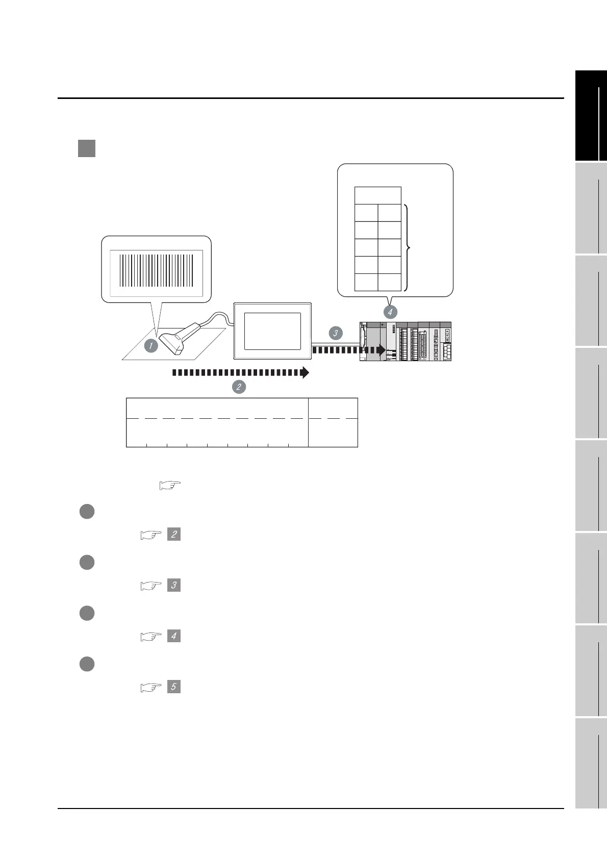
A system configuration example for bar code reader connection is shown below.
1 System Configuration
*1 The GOT asnd QCPU (Q mode) are connected through a bus.
For bus connection, refer to the following.
Chapter 2 BUS CONNECTION
1 The bar code is read with the bar code reader.
Bar code reader setting
2 The GOT receives the data sent from the bar code reader.
"Communication settings" in GT Designer2
3 The received data are written to the PLC CPU.
"Bar Code" in GT Designer2
4 The data read with the bar code reader are written into the PLC CPU devices.
Confirmation on PLC side
123456789
Barcode
<GOT>
<QCPU (Q mode)>
Read data Terminator
CR
0D
H
1
31
H
2
32
H
3
33
H
4
34
H
5
35
H
6
36
H
7
37
H
8
38
H
9
39
H
*1
Read data
"123456789"
D0
D1
D2
D3
D4
D5
9
(00
H)(09H)
2
(32
H)
1
(31H)
3
(33
H)
4
(34H)
5
(35
H)
6
(36H)
7
(37
H)
8
(38H)
9
(39
H)
SP
(20
H)
Read bytes
Stored data
 Loading...


