31.1 System Configuration
31 - 5
25
BAR CODE READER
CONNECTION
26
PRINTER CONNECTION
27
CNC CONNECTION
28
MULTI-CHANNEL
FUNCTION
29
FA TRANSPARENT
FUNCTION
30
MULTIPLE-GT11
CONNECTION FUNCTION
31
GATEWAY FUNCTION INDEX
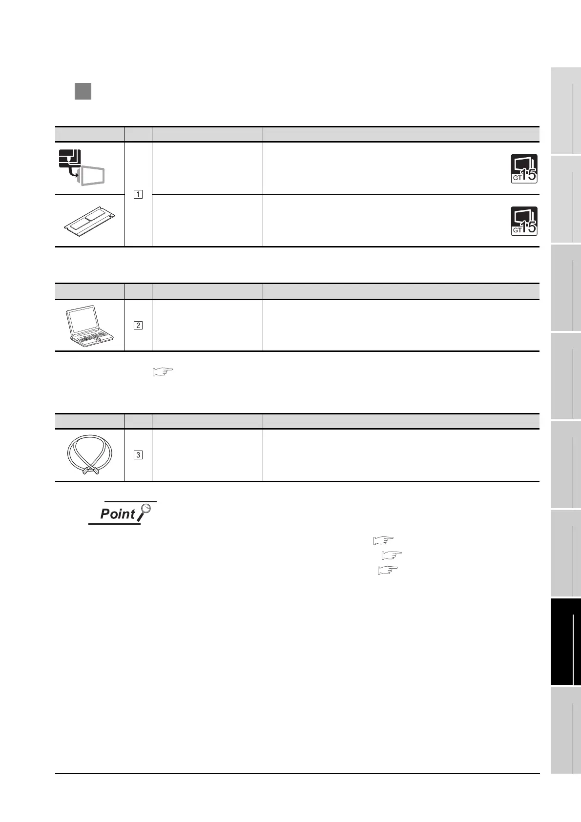
2 System equipment
(1) GOT
(2) PC
*1 For the accessing range for use of the gateway function, refer to the following manual.
GOT1000 Series Gateway Functions Manual.
(3) Cable
(1) System configuration between the GOT and PLC
For the system configuration between the GOT and PLC, refer to each chapter.
• MITSUBISHI PLC CONNECTIONS ( Chapter 2 to Chapter 8)
• THIRD PARTY PLC CONNECTIONS ( Chapter 9 to Chapter 17)
• MICROCOMPUTER CONNECTION ( Chapter 19)
(2) System configuration for use of the mail send function
The SMTP mail server must be established in the intranet to use the mail send
function.
Image No. Name Model name
Ethernet communication unit
• For Ethernet communication
GT15-J71E71-100
Option function board
• For optional function
GT15-FNB, GT15-QFNB, GT15-QFNB16M,
GT15-QFNB32M, GT15-QFNB48M
Image No. Name Model name
PC
Software to be used: MX Component, Version 3 or later
*1
Image No. Name Model name
Twisted pair cable
Shielded twisted pair cable (STP) or unshielded twisted pair cable in category
(UTP): 3, 4 and 5
Ethernet
 Loading...


