6 - 28
6.3 PLC Side Setting
6.3.2 Connecting to CC-Link module (QnA Series)
3 Parameter setting
There are two methods for the parameter setting: perform the setting from [Network parameter] of GX
Developer and the sequence program.
Performing it from the [Network parameter] of the GX Developer can be set only when the PLC CPU
and the CC-Link module use the function version B or later.
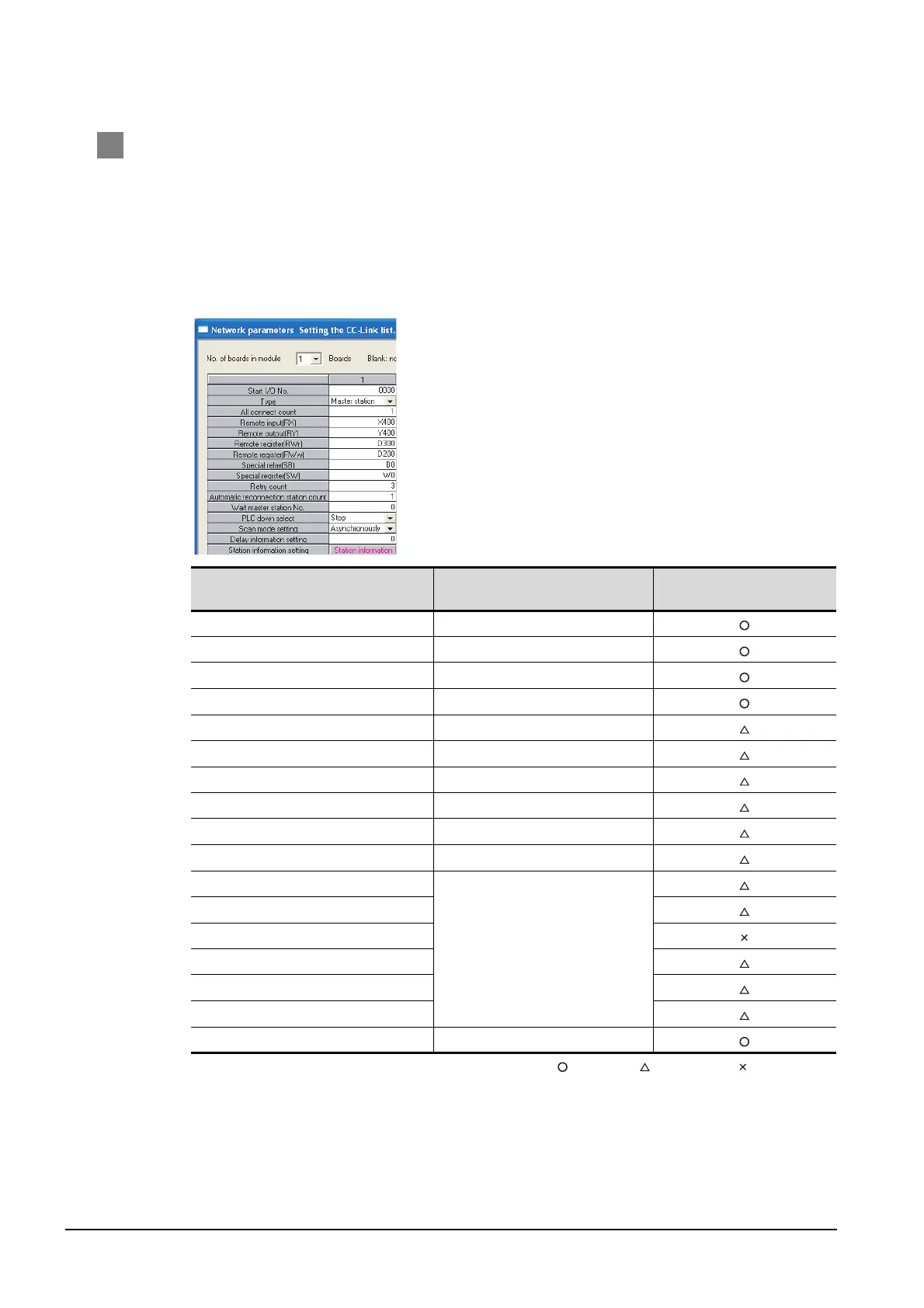
(1) Setting from [Network parameter] of GX Developer
(a) Network parameter
: Necessary : As necessary : Not necessary
Item Setting
Setting necessity at GOT
connection
No. of boards in module 1
Start I/O No. 0000H
Type Master station (fixed)
All connect count 1
Remote input (RX) X400
Remote output (RY) Y400
Remote register (RWr) D300
Remote register (RWw) D200
Special relay (SB) B0
Special register (SW) W0
Retry count
(Use default value.)
Automatic reconnection station count
Wait master station No.
PLC down select
Scan mode setting
Delay information setting
Station information setting Refer to (2).

 Loading...


