8.1 System Configuration
8 - 3
1
OVERVIEW
2
BUS CONNECTION
3
DIRECT CONNECTION
TO CPU
4
COMPUTER LINK
CONNECTION
5
MELSECNET/10
CONNECTION (PLC TO
PLC NETWORK)
6
CC-Link CONNECTION
(INTELLIGENT DEVICE
STATION)
7
CC-Link CONNECTION
(Via G4)
8
ETHERNET
CONNECTION
2 System equipment
(1) GOT
(2) PLC
*1 For the system configuration of the Ethernet module, refer to the following manuals.
• Q Corresponding Ethernet Interface Module User’s Manual (Basic)
• For QnA Ethernet Interface Module User
's Manual
• For A Ethernet Interface Module User’s Manual
*2 Select one of the following [Type] in [Ethernet setting] of GT Designer2.
• Ethernet
module (Q Series) : QJ71E71
• Ethernet
module (QnA Series) : AJ71QE71
• Ethernet
module (QnA Series) : AJ71E71
For [Ethernet setting] of GT Designer2, refer to the following.
Section 8.2.3 Setting communication interface (Communication settings)
(3) Cable
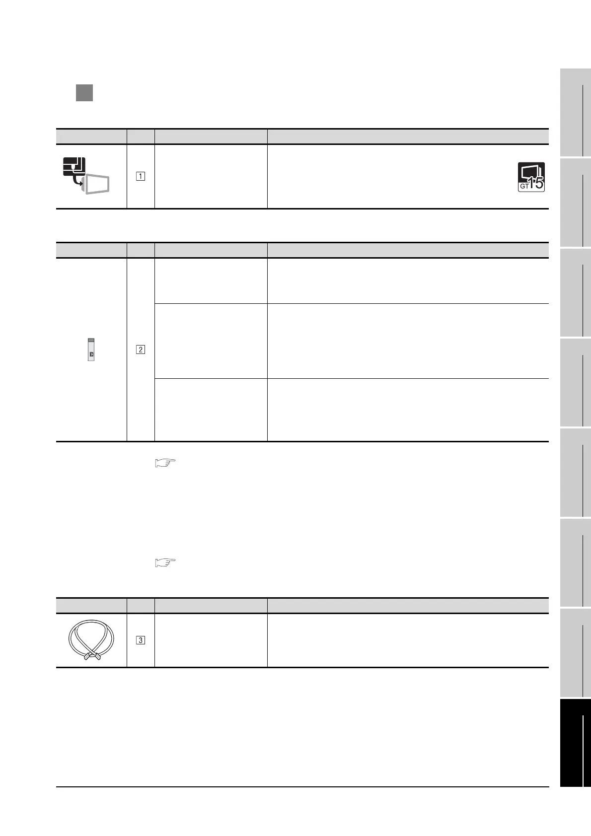
Image No. Name Model name
Ethernet communication unit
• For Ethernet communication
GT15-J71E71-100
Image No. Name Model name
Ethernet module
(Q Series)
*1 *2
QJ71E71-100, QJ71E71-B5, QJ71E71-B2,
QJ71E71
Ethernet module
(QnA Series)
*1 *2
AJ71QE71N3-T, AJ71QE71N-B5, AJ71QE71N-B2,
AJ71QE71N-T, AJ71QE71N-B5T,
AJ71QE71, AJ71QE71-B5,
A1SJ71QE71N3-T, A1SJ71QE71N-B5, A1SJ71QE71N-B2,
A1SJ71QE71N-T, A1SJ71QE71N-B5T,
A1SJ71QE71-B5, A1SJ71QE71-B2
Ethernet module
(A Series)
*1 *2
AJ71E71N3-T, AJ71E71N-B5, AJ71E71N-B2,
AJ71E71N-T, AJ71E71N-B5T, AJ71E71-S3,
A1SJ71E71N3-T, A1SJ71E71N-B5, A1SJ71E71N-B2,
A1SJ71E71N-T, A1SJ71E71N-B5T,
A1SJ71E71-B5-S3, A1SJ71E71-B2-S3
Image No. Name Model name
Twisted pair cable
Shielded twisted pair cable (STP) or unshielded twisted pair cable in category
(UTP): 3, 4 and 5
Ethernet

 Loading...


