22 - 10
22.2 Connection Cable
22.2.1 RS-232 cable
22.2.1 RS-232 cable
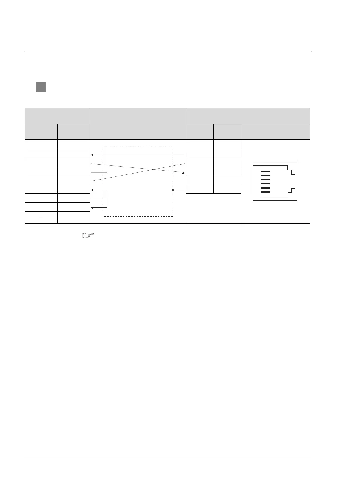
The following shows the connection diagrams and connector specifications of the RS-232 cable used for
connecting the GOT to a temperature controller.
1 Connection diagram
(1) RS-232 cable 1)
*1 For details of the pin assignment, refer to the following manual.
User's Manual for the RKC temperature controller
GOT side
Cable connection and signal direction
RKC product side
(Modular connector)
Signal name Pin No. Pin No.
Signal
name
Pin assignment
*1
CD 1 1 NC
RD(RXD) 2 2 SD
SD(TXD) 3 3 SG
ER(DTR) 4 4 RD
SG 5 5 NC
DR(DSR) 6 6 SG
RS(RTS) 7
CS(CTS) 8
9
SG
Unused
RD
SG
SD
Unused
6
5
4
3
2
1
 Loading...


