22.2 Connection Cable
22 - 9
17
CONNECTION TO
ALLEN-BRADLEY PLC
18
CONNECTION TO
SIEMENS PLC
19
MICROCOMPUTER
CONNECTION
20
CONNECTION TO OMRON
TEMPERATURE
CONTROLLER
21
CONNECTION TO
YAMATAKE TEMPERATURE
CONTROLLER
22
CONNECTION TO RKC
TEMPERATURE
CONTROLLER
23
CONNECTION TO
FREQROL SERIES
INVERTER
24
SERVO AMPLIFIER
CONNECTION
22.2 Connection Cable
The RS-232 cable or RS-422 cable, or RS-485 cable used for connecting the GOT to the temperature con-
troller should be prepared by the user. The following provides connection diagrams for each cable, connector
specifications and other information.
*1 For H-PCP-J, select the following models.
*2 For H-PCP-A and H-PCP-B, select the following models.
For details of the models, refer to the following manual.
User's Manual for the RKC temperature controller
Model name
Connection cable
RS-232 cable
(Section 22.2.1)
RS-422 cable
(Section 22.2.2)
RS-485 cable
(Section 22.2.3)
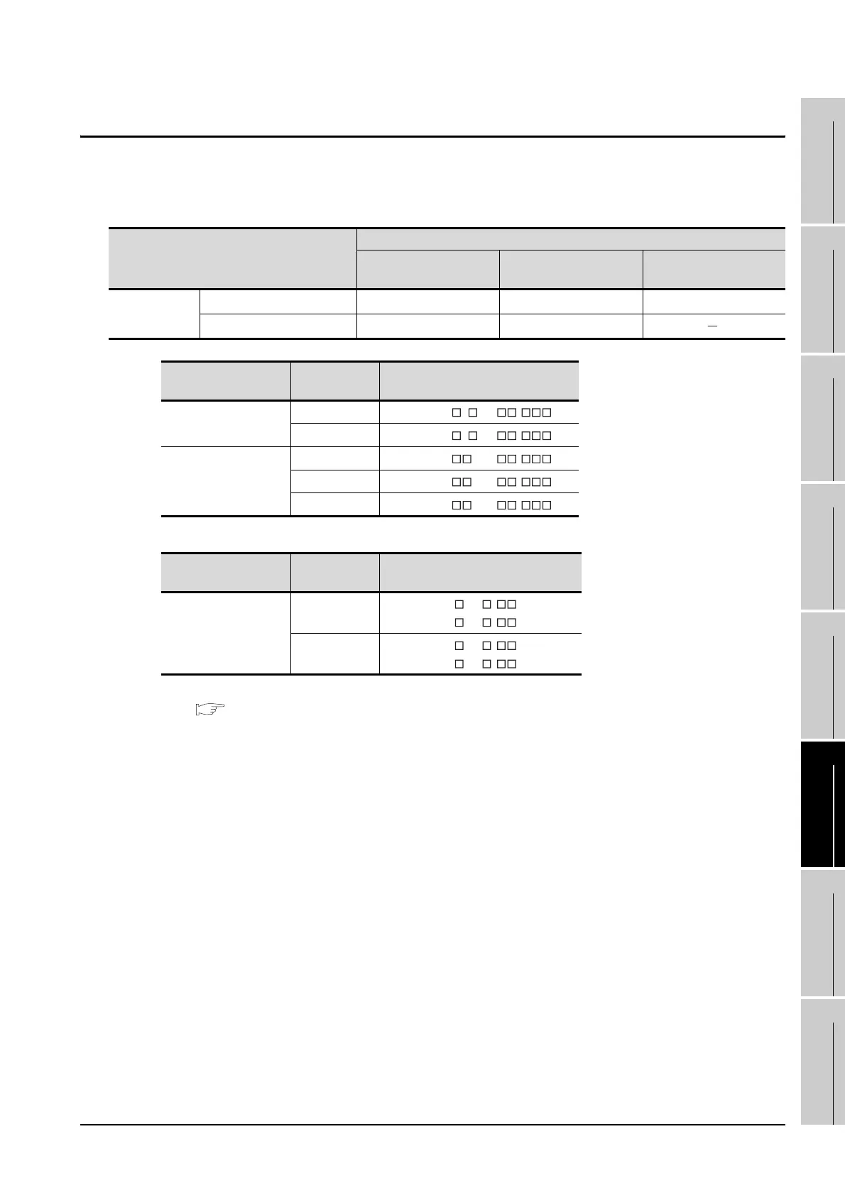
Temperature
controller
H-PCP-J
*1
RS-232 cable 1) RS-422 cable 1) RS-485 cable 1)
H-PCP-A
*2
, H-PCP-B
*2
RS-232 cable 1) RS-422 cable 1)
Connector
Communication
format
Models
COM.PORT1
COM.PORT2
RS-422
H-PCP-J- 4 -D * -
RS-485
H-PCP-J- 5 -D * -
COM.PORT3
RS-232
H-PCP-J- 1-D * -
RS-422
H-PCP-J- 4-D * -
RS-485
H-PCP-J- 5-D * -
Connector
Communication
format
Models
Modular connector1
RS-232
H-PCP-A- 1N- * Z-1021
H-PCP-B- 1N- * Z-1021
RS-422
H-PCP-A- 4N- * Z-1021
H-PCP-B- 4N- * Z-1021
 Loading...


